
Compact maxillary distractor

a distractor and compact technology, applied in the field of orthognathic systems, can solve the problems of limited orthognathic procedures involving maxillary advancement, limited maxilla advancement, and limited maxilla growth, and achieve the effect of increasing the separation of the maxilla and the zygoma

Inactive Publication Date: 2005-06-21
SYNTHES USA +1
View PDF57 Cites 63 Cited by
  • Summary
  • Abstract
  • Description
  • Claims
  • Application Information

AI Technical Summary

Benefits of technology

[0016]In another embodiment, an orthopedic device is provided for modifying the distance between first and second bone segments of a patient, the system comprising a first footplate for subcutaneous implantation and attachment to the first bone segment, the first footplate having bone attachment and actuator attachment portions. A second footplate may be provided for subcutaneous implantation and attachment to the second bone segment, the second footplate having bone attachment and actuator attachment portions. An actuator having first and second ends also may be provided, wherein the first footplate actuator attachment portion engages the actuator between the actuator first and second ends, and the second footplate actuator attachment portion engages the actuator substantially adjacent to or at the second end, and wherein the second footplate actuator attachment portion is configured to be removably engageable with the actuator.
[0022]An additional method is provided for distracting the maxilla from the zygoma of a patient comprising the steps of: making at least one incision to expose the maxilla and zygoma; selecting first and second distraction assemblies comprising first and second footplates and an actuation assembly; aligning the first and second distraction assemblies on the patient's maxilla and zygoma; removing the first and second distraction assemblies from the patient; performing an osteotomy separating the maxilla from the zygoma; attaching the first and second distraction assemblies to the patient's zygoma using screws so that at least a portion of each assembly is located behind the zygoma; mechanically coupling the first and second distraction assemblies to the patient's maxilla using screws; closing the at least one incision, and leaving at least a portion of the distraction assembly of each device exposed; performing a distraction procedure, using the distraction assemblies to increase the separation of the maxilla from the zygoma; allowing time for consolidation; and removing the devices from the patient.

Problems solved by technology

These procedures involve a great deal of soft tissue dissection, and leave the patient with significant scar tissue surrounding their maxillary region.
As a result of the reduced elasticity of the scar tissue as compared to regular soft tissue, the maxilla is very often restricted from normal growth and can be very difficult to advance using conventional orthognathic surgery (surgery relating to treatment of the malpositioning of bones of the jaw).
Typically, orthognathic procedures involving maxillary advancements are limited in the magnitude of the advancement of the maxilla due to the elastic properties of the surrounding soft tissues.
However, the only available devices that can be used for maxillary distraction have external “halo-style” fixators that attach to the skull and to the maxilla by way of surgical wires affixed to an intra-oral appliance.
Such a high profile external device is unsightly, and the psychosocial effects of wearing an external device is a major concern, especially with younger patients.
An external device is also more subject to bumps and snags than one which is completely located within a patient's body.
Furthermore, the known external fixators involve a large number of component parts and accordingly are complicated to install and adjust.
Furthermore, there is a need for a distractor which occupies as little space as possible in the patient's mouth, even when the device is extended to its full length.

Method used


Image

  • Compact maxillary distractor
  • Compact maxillary distractor
  • Compact maxillary distractor

Examples


Embodiment Construction

[0043]The orthopedic device of the present invention is discussed herein with reference to a preferred embodiment adapted to be used in a linear distraction of the maxilla from the zygoma.

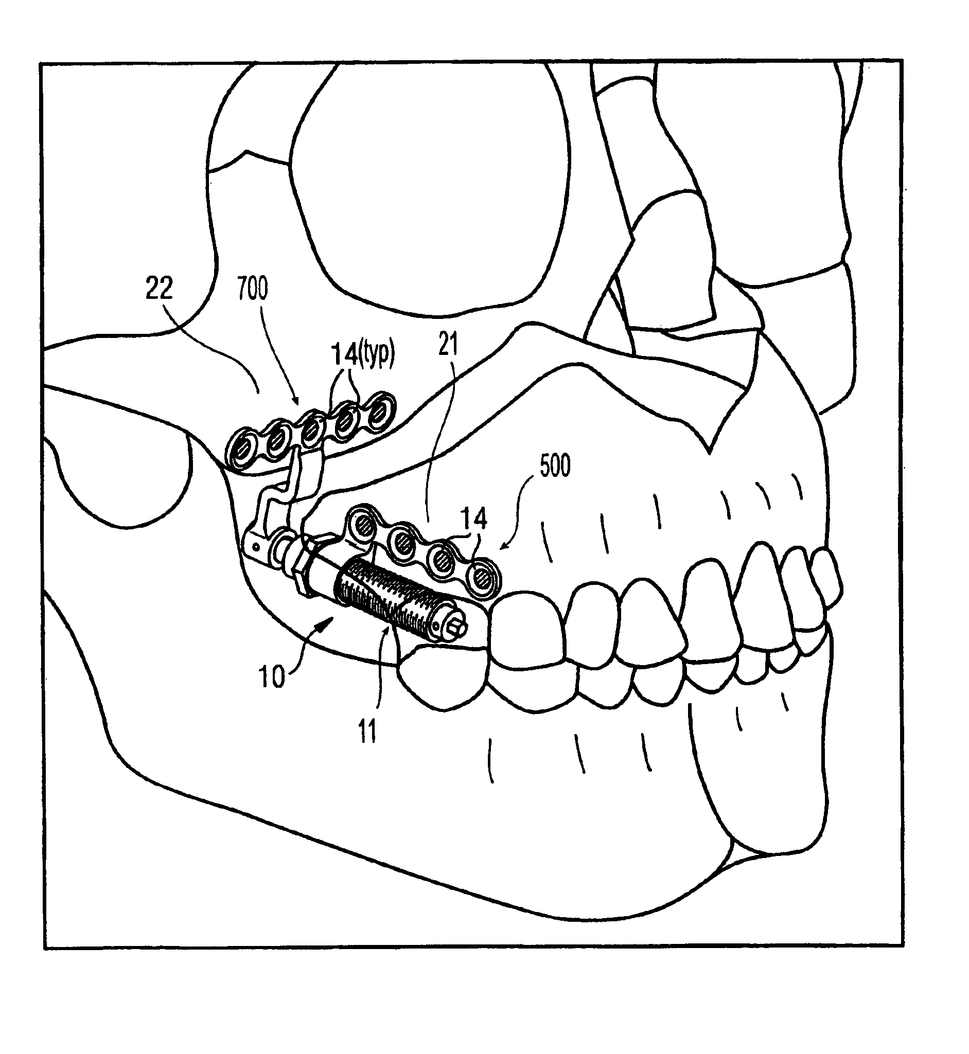
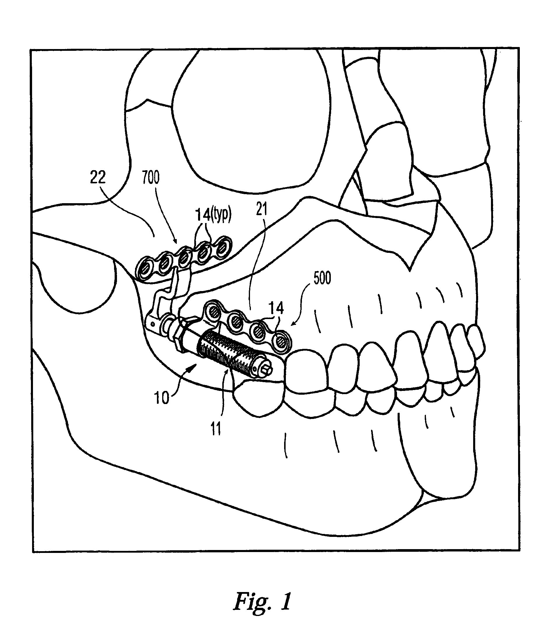
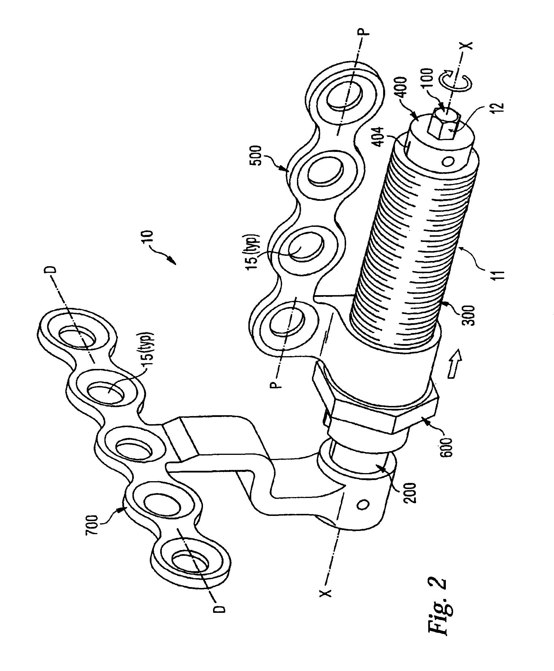
[0044]As seen in FIGS. 1, 2, and 3a, the orthopedic system 10 generally consists of distraction assembly 11 and anchors in the form of proximal and distal bone plates 500 and 700, respectively. The distraction assembly 11 has a proximal, or adjustment end 12 and a distal end 13. The orthopedic system 10 is affixed to maxilla 21 and zygoma 22 by bone screws 14 which are inserted though screw-holes 15 in footplates 500 and 700. In use, the entire orthopedic system 10 is implanted so that the distal bone plate 700 is attached to the zygoma 22 and the proximal bone plate 500 is attached to the maxilla 21, with the distraction assembly 11 nestled within the buccal sulcus. It will be understood that with reference to the various elements of the present invention, the term proximal is used to refer to the...


PUM


Abstract

The present invention provides an improved orthopedic system for the modification of the distance between the maxilla and zygoma. In a preferred embodiment, the system includes first and second footplates attached to an orthopedic device. The second footplate is attached to the zygoma, with the first footplate being mechanically coupled to the maxilla. This mechanical coupling is achieved either through attachment directly to the maxilla or by attachment to a construct wired to the patient's teeth. The orthopedic device, which may be a distractor, allows for modification of the distance between the maxilla and zygoma. The entire system can advantageously be placed intra-orally within a patient. In a preferred embodiment, the device does not increase in length upon activation. In another preferred embodiment, the second footplate is offset, allowing the actuator to be placed under the zygoma. Methods for using this novel orthopedic system are also disclosed.

Description

CROSS-REFERENCE TO RELATED APPLICATIONS[0001]This is a continuation-in-part of U.S. application Ser. No. 09 / 971,216 filed Oct. 3, 2001 now abandoned, which claims the benefit of U.S. Provisional Application No. 60 / 237,519 filed Oct. 4, 2000.FIELD OF INVENTION[0002]The present invention relates to an orthopedic system and, more particularly, to an improved orthopedic system wherein the device is used intra-orally in a patient to achieve a change in the position of the maxilla (upper jawbone) in relation to the zygoma (cheekbones).BACKGROUND OF THE INVENTION[0003]A variety of orthopedic devices, including bone reduction and distraction devices, are known in the art. Reduction and distraction devices (commonly referred to as reducers and distractors), are used to gradually adjust the relative orientation and spacing of the bone parts on opposing sides of a bone repair site. As used herein, “bone repair site” refers to any bone region which is bounded on opposing sides by relatively hea...

Claims


Application Information

Patent Timeline
IPC IPC(8): A61B17/60A61B17/66A61B17/00A61B17/56A61B17/24
CPCA61B17/663A61B2017/00004
Inventor SELLERS, TIMOTHY M.NOON, JOHN M.HAAG, RENE
Owner SYNTHES USA
Learn More