Cooking chamber assembly in microwave oven

a technology of microwave oven and chamber assembly, which is applied in the direction of stove/range foundation, electrical/magnetic/electromagnetic heating, electrical apparatus, etc., can solve the problems of rust, failure to cover the abutting parts of the gasket, and inconvenient application of sealant in the above structure, etc., to achieve the effect of improving the structur

Inactive Publication Date: 2005-06-21
LG ELECTRONICS INC
View PDF5 Cites 22 Cited by
  • Summary
  • Abstract
  • Description
  • Claims
  • Application Information

AI Technical Summary

Benefits of technology

[0015]An object of the present invention, designed for solving the foregoing problems, lies on providing a cooking chamber assembly in a microwave oven, which has an improved structure that can prevent formation of a gap between a wall of a cooking chamber case and a tray.

Problems solved by technology

However, the application of the sealant is not convenient in above structure, failing to cover the abutting parts of the gaskets 55, perfectly.
Then, water or dirt may infiltrate therein, which is not sanitary, and may caused rust, or out of order of components when intensive.
Moreover, the applied sealant 56 or the gap 57 harms a sense of beauty of the cooling chamber 20, and drops consumer satisfaction.
However, such a fastening structure requires many assembly components, and a complicated assembly process, and time, which drops productivity.

Method used


Image

  • Cooking chamber assembly in microwave oven
  • Cooking chamber assembly in microwave oven
  • Cooking chamber assembly in microwave oven

Examples


Embodiment Construction

[0040]Reference will now be made in detail to the preferred embodiments of the present invention, examples of which are illustrated in the accompanying drawings. In describing the present invention, same parts will be given the same names and symbols, and repetitive description of which will be omitted.

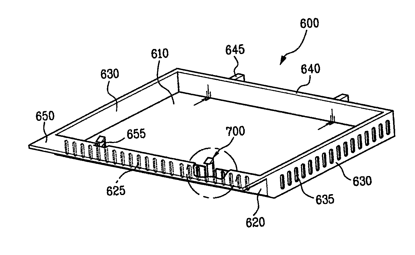
[0041]FIG. 5 illustrates a disassembled perspective view showing a ceiling structure between an inner case of a cooking chamber and a tray in accordance with a preferred embodiment of the present invention schematically, FIG. 6 illustrates a section across a line I—I in FIG. 5, and FIG. 7 illustrates a section across a line II—II in FIG. 5. Those drawings show a tray 400 mounting structure in a cooking chamber assembly of a microwave oven of the present invention, well.

[0042]Referring to FIG. 5, the cooking chamber assembly includes an inner case 200, a tray 400, and a gasket 500.

[0043]The inner case 200 is mounted on the base plate 100. A cooking chamber 210 is formed inside of the i...


PUM


Abstract

A cooking chamber assembly in a microwave oven for improved which improves air tightness in the cooking chamber, and reduces assembly complexity, time, and cost. A tray which essentially forms a bottom surface of a cooking chamber of the microwave oven is surrounded by a unitary gasket. A groove formed in an inner edge of the unitary gasket is designed to receive an outer edge of the tray, and a lip formed on an outer edge of the unitary gasket is designed to provide an air tight seal with an inner surface of a case of the cooking chamber. An air duct which guides circulating air is attached to an inner portion of the case with a series of hooks, allowing the air duct to be attached without separate fastening members such as screws or bolts, thus further reducing manufacturing time and cost.

Description

[0001]This application claims the benefit of the Korean Application Nos. P2002-85106 filed on Dec. 27, 2002, and P2002-86907 filed on Dec. 30, 2002, which are hereby incorporated by reference.BACKGROUND OF THE INVENTION[0002]1. Field of the Invention[0003]The present invention relates to microwave ovens, and more particularly, to a cooking chamber assembly in a microwave oven of which ceiling and air duct assembly are improved.[0004]2. Background of the Related Art[0005]The microwave oven defrosts or heats food by directing a microwave to the food, that causes molecules in the food to vibrate to generate frictional heat for the defrosting or the heating.[0006]FIG. 1 illustrates a partly disassembled perspective view of a related art microwave oven. As shown, the microwave oven is provided with a base plate 10, a front plate 15 and a rear plate 13 mounted on a front end and a rear end of the base plate 10 vertical thereto respectively, an inner case 17 between the front plate 15 and ...

Claims


Application Information

Patent Timeline
Patent Type & Authority Patents(United States)
IPC IPC(8): F24C15/08H05B6/80
CPCH05B6/6408H05B6/6426H05B6/642
Inventor LEE, SANG RYULLEE, DUCK GIL
Owner LG ELECTRONICS INC
Why Eureka
Try Eureka