Web velocity-based registration control system

a control system and registration technology, applied in the field of web velocity-based registration control system, can solve the problems of insufficient effectiveness of conventional devices and systems, such as those described above, insufficient control of process operations and archive registration, and many imaging systems are bulky and difficult to use in limited spaces

Inactive Publication Date: 2005-06-21
KIMBERLY-CLARK WORLDWIDE INC
View PDF11 Cites 29 Cited by
  • Summary
  • Abstract
  • Description
  • Claims
  • Application Information

AI Technical Summary

Benefits of technology

[0007]An apparatus aspect can include a transporter which can move the web along a movement direction past a reference detector. The reference detector can be configured to detect at least a first reference point on the web, and the first reference point can be employed in a designating of the target point. The web can be transported past a speed-sensor which is capable of measuring a web speed of the moving web to provide web speed data. In a particular aspect, an integrato

Problems solved by technology

Conventional devices and system, such as those described above, have not been sufficiently effective for inspecting the registration and location of component elements on a moving web.
The systems have not been sufficiently able to control the registration of process operations and archive the registration data.
Many imaging systems have been bulky and have been difficult to use in limited spaces.
In addition, the conventional systems have not been sufficiently accurate, particularly when there have been extended distances between the locations of control sensors and the locations of their associated production operations.
The systems have been susceptible to errors caused by various factors.
Such factors ca

Method used


Image

  • Web velocity-based registration control system
  • Web velocity-based registration control system
  • Web velocity-based registration control system

Examples


Embodiment Construction

[0035]The present disclosure of the invention will be expressed in terms of its various components, elements, constructions, configurations, arrangements and other features that may also be individually or collectively be referenced by the term, “aspect(s)” of the invention, or other similar terms. It is contemplated that the various forms of the disclosed invention may incorporate one or more of its various features and aspects, and that such features and aspects may be employed in any desired, operative combination thereof.

[0036]It should also be noted that, when employed in the present disclosure, the terms “comprises”, “comprising” and other derivatives from the root term “comprise” are intended to be open-ended terms that specify the presence of any stated features, elements, integers, steps, or components, and are not intended to preclude the presence or addition of one or more other features, elements, integers, steps, components, or groups thereof.

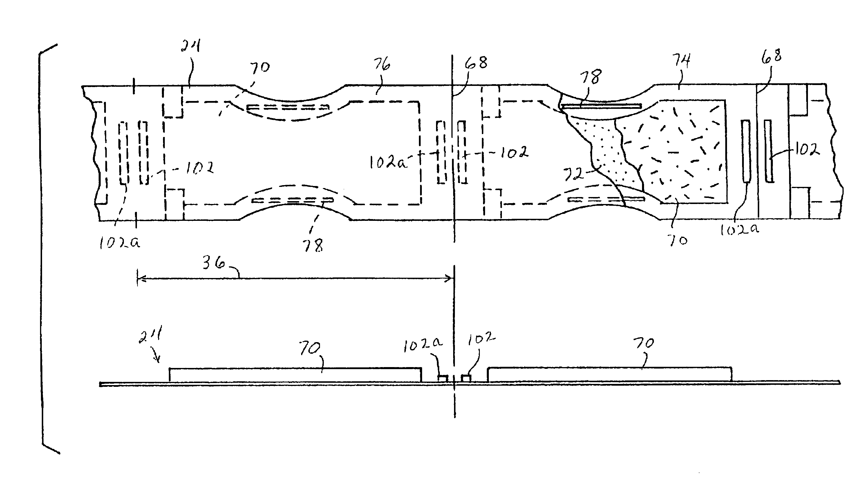
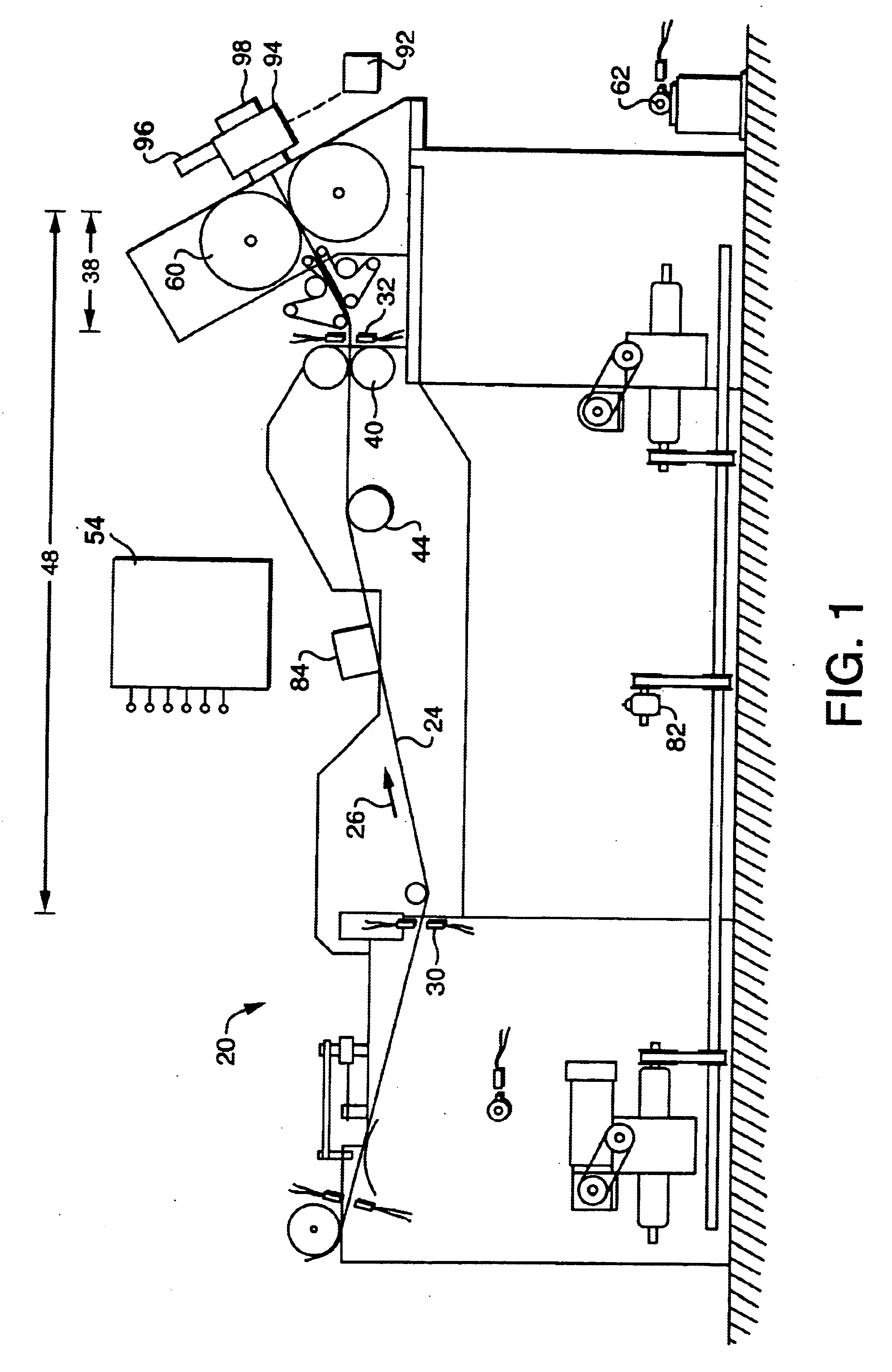
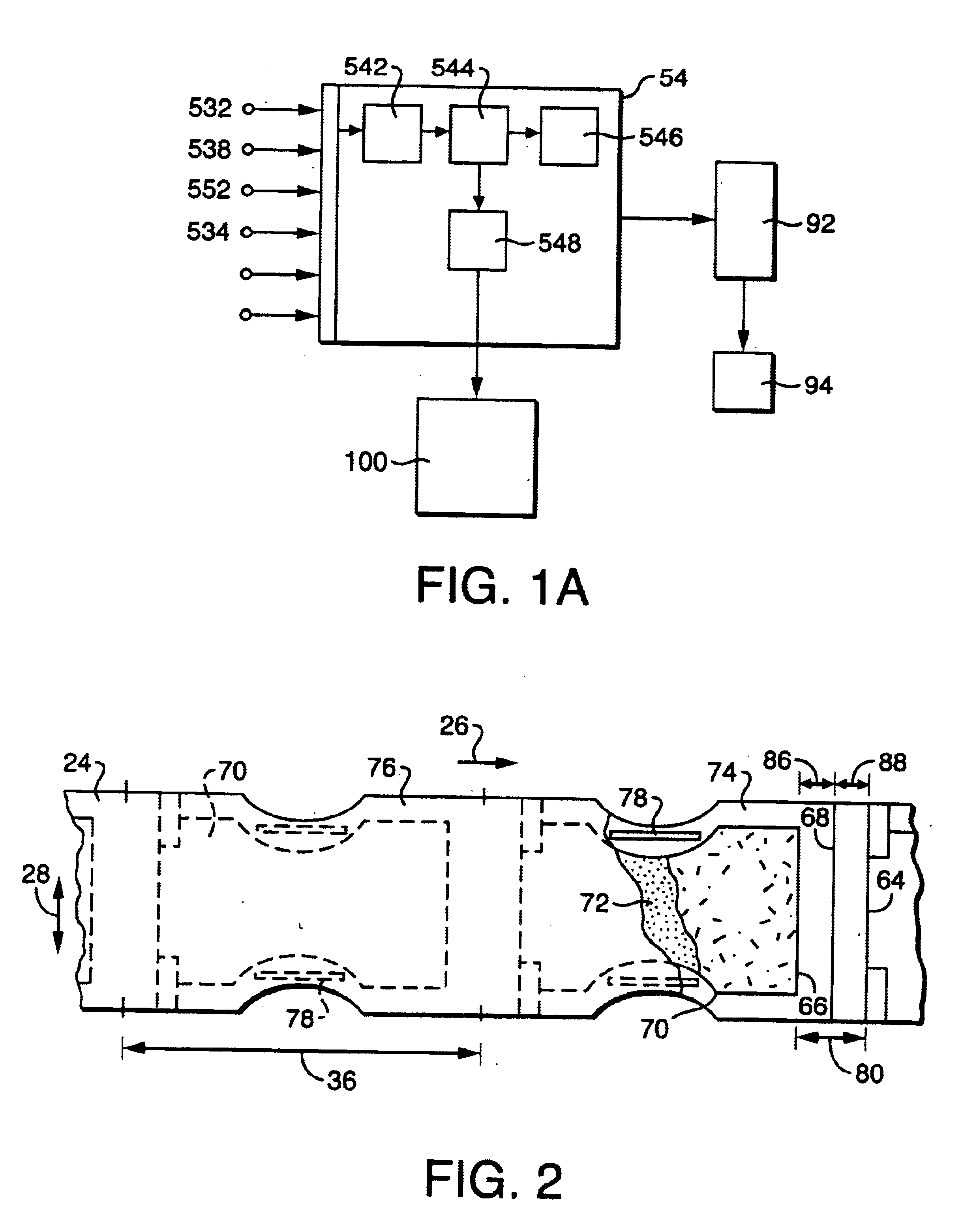
[0037]With reference to FIG...


PUM


Abstract

The present invention provides a method and apparatus (20) for controlling a registration between a target point (22) on a moving web (24), and a production outcome provided by a production operation. A method aspect can include a transporting of the web (24) along a movement direction (26) past a reference detector (30), and a detecting of at least a first reference point (50) on the web (24). The target point (22) can be designated by employing at least the first reference point (50). The web is transported past a speed-sensor (32), and the speed-sensor can measure a web speed of the moving web (24) to provide an output of web speed data. The web speed data is integrated over time to determine a web-length which has been transported past the speed-sensor (32). The production outcome is actuated at a production-device (34), and the actuating of the production outcome can be adjusted to occur after a reference-length of the web (24) has been transported past the speed-sensor (32).

Description

FIELD OF THE INVENTION[0001]The present invention relates to a method and apparatus for inspecting a moving web, and controlling the locations of selected component elements. Additionally, the present invention can relate to a method and apparatus for controlling the locations and positioning the outcomes provided by selected processing operations.BACKGROUND OF THE INVENTION[0002]Conventional devices and systems have been employed for controlling the placement and positioning of selected components on a moving composite web, and for controlling selected processing operations, such as cutting operations. Such systems have been employed to produce absorbent articles, such as disposable diapers, adult incontinence products and feminine care products. The systems have typically tracked the moving web by using time-counts and encoder-counts.[0003]Systems that incorporate electromagnetic radiation shifting indicia have also been employed. The indicia have provided signals which have been ...

Claims


Application Information

Patent Timeline
IPC IPC(8): B65H23/188G01P3/36G01B21/06
CPCA61F13/15772B65H23/1882B65H2511/11B65H2511/22B65H2511/512B65H2513/104B65H2801/57B65H2220/02B65H2220/01B65H2513/10
Inventor UNGPIYAKUL, TANAKONBETT, THOMAS A.
Owner KIMBERLY-CLARK WORLDWIDE INC
Why Eureka
Try Eureka