Stator sub-assembly, stator assembly, motor and manufacturing method of stator assembly

a stator assembly and sub-assembly technology, applied in the direction of horology, magnetic circuit shape/form/construction, instruments, etc., can solve the problems of reducing the reliability of soldering, reducing the manufacturing reliability of stator assembly and motor, and difficult or complicated to make a smooth electrical connection. , to achieve the effect of high reliability

Active Publication Date: 2005-06-21
MINEBEAMITSUMI INC
View PDF12 Cites 34 Cited by
  • Summary
  • Abstract
  • Description
  • Claims
  • Application Information

AI Technical Summary

Benefits of technology

[0013]The present invention has been made in the light of the above, and its object is to provide a stator sub-assembly, a stator assembly, and a motor which allow them to have their respective smooth electrical connections with an apparatus on which they are mounted and also to provide a method of manufacturing a highly-reliable stator.

Problems solved by technology

Consequently, it is difficult or complicated to make a smooth electrical connection between the stepping motor provided with the above-described stator assembly 100 and an apparatus on which the stepping motor is mounted.
However, enlarging the connection holes involves defects such as incomplete soldering, thereby diminishing the reliability of soldering.
In brief, the conventional stator assembly 100 has a defect in that the dislocation between the two terminal blocks 107 and 107 opposite to each other can occur, causing the defects of the electrical connection between the motor having the stator assembly 100 and the apparatus on which the motor is mounted, eventually diminishing the manufacturing reliability of the stator assembly and the motor.

Method used


Image

  • Stator sub-assembly, stator assembly, motor and manufacturing method of stator assembly
  • Stator sub-assembly, stator assembly, motor and manufacturing method of stator assembly
  • Stator sub-assembly, stator assembly, motor and manufacturing method of stator assembly

Examples


Embodiment Construction

[0044]Preferred embodiments of the present invention will hereinafter be explained with reference to the accompanying drawings.

[0045]In the following preferred embodiments, a PM stepping motor using a permanent magnet and used as a rotating component or the like of an OA apparatus or an automobile will be discussed as an example.

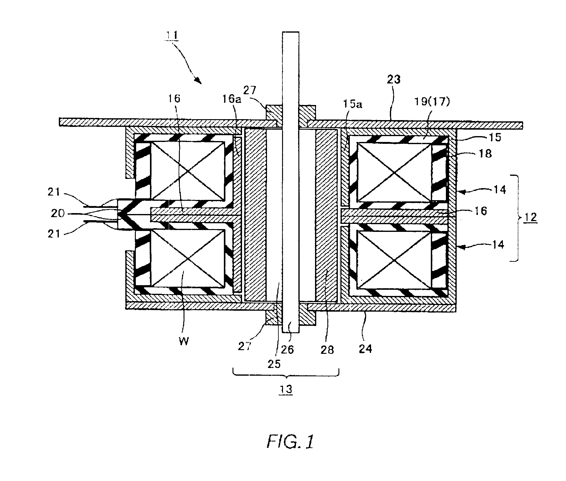
[0046]FIG. 1 shows a cross-sectional structure of a stepping motor 1 generally comprising a stator assembly 12 and a rotor assembly 13.

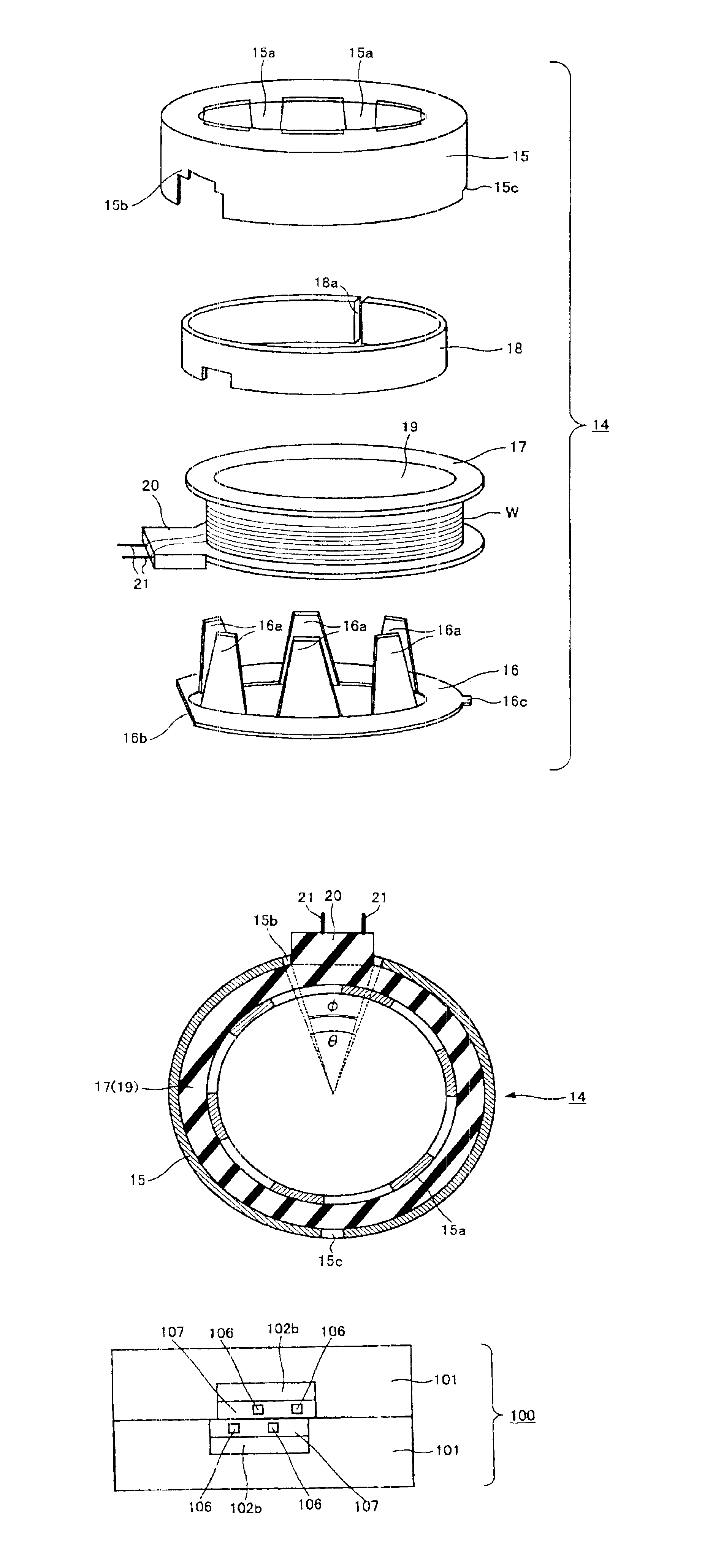
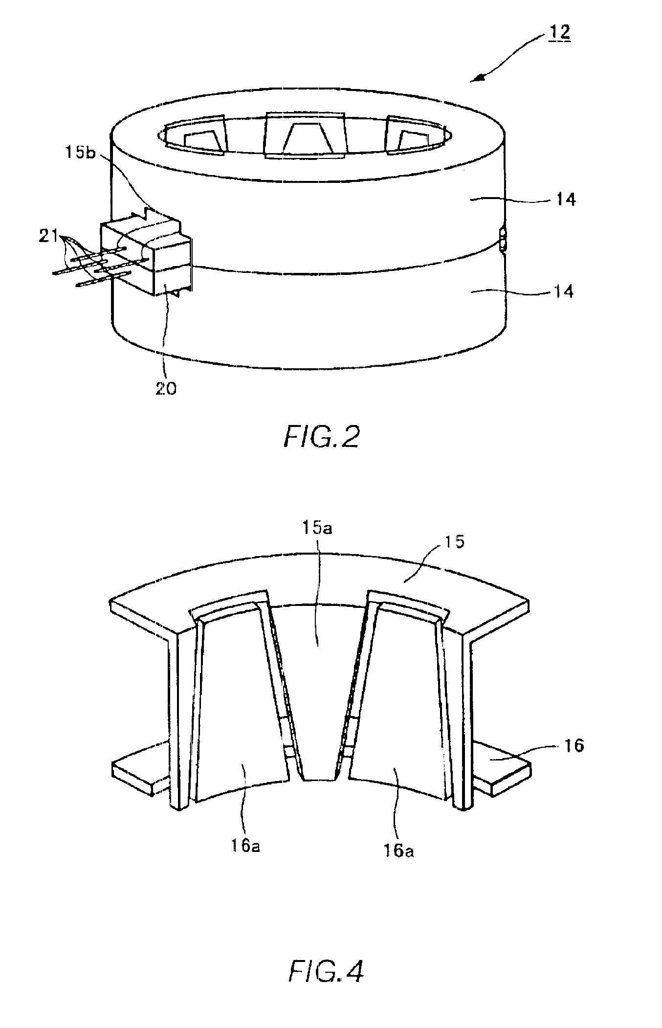
[0047]Referring to FIG. 2, the stator assembly 12 is formed such that two stator subassemblies 14 and 14 are superimposed back to back. As shown in an exploded view of FIG. 3, the stator subassembly 14 comprises an outer stator yoke 15, an inner stator yoke 16, a coil bobbin 17 and a cover ring 18.

[0048]The outer stator yoke 15 constitutes a periphery and top surface of the stator subassembly 14, and is made of a cup-shaped, cylindrical soft magnetic steel plate, and has a plurality of first pole teeth 15a formed along its an...


PUM


Abstract

A stator sub-assembly comprises: a coil bobbin which is composed of a cylinder having a winding of a magnet wire therearound, and a terminal block provided with terminal pins connected to lead wires of the winding and coupled stator yokes housing said coil bobbin therein and having a cutout for allowing the terminal block to protrude therethrough. The cutout has a width adapted to allow the terminal block to circumferentially shift rotationally about the center of an axial direction of the coil bobbin.

Description

BACKGROUND OF THE INVENTION[0001]1. Field of the Invention[0002]The present invention relates to a stator sub-assembly, a stator assembly, a motor using the same, and a manufacturing method of the stator assembly.[0003]2. Description of the Related Art[0004]A stepping motor has been extensively used as a motor used for a rotating component and the like of an OA apparatus or an automobile. The stepping motor converts a digital electric input into a mechanical motion in response to electric signals and rotates stepwise by a fixed angle for each step, thus attaining a high accuracy in positioning. One type of such a stepping motor is a PM (permanent magnet) stepping motor using a permanent magnet in a rotor section thereof.[0005]A conventional PM stepping motor is provided with a stator assembly 100 as shown in FIG. 10. The stator assembly 100 comprises two stator subassemblies 101 and 101 attached back to back.[0006]FIG. 11 shows an exploded view of one of the two stator subassemblies...

Claims


Application Information

Patent Timeline
Patent Type & Authority Patents(United States)
IPC IPC(8): H02K3/52H02K3/46H02K37/14
CPCH02K3/525
Inventor SUZUKI, YUZURUOHYASHIKI, TAKETOSHI
Owner MINEBEAMITSUMI INC
Why Eureka
Try Eureka