
Ladder-type filter, branching filter, and communication device

a branching filter and ladder-type technology, applied in the direction of piezoelectric/electrostrictive/magnetostrictive devices, electrical apparatus, impedence networks, etc., can solve the problems that the attenuation in the blocking band is at least 40 db and cannot be satisfied with ladder-type filters known, so as to increase the attenuation in the blocking band on the lower frequency side with respect to the pass-band and increase the pass-band width

Inactive Publication Date: 2005-06-21
MURATA MFG CO LTD
View PDF14 Cites 40 Cited by
  • Summary
  • Abstract
  • Description
  • Claims
  • Application Information

AI Technical Summary

Benefits of technology

The present invention provides a ladder type filter with improved performance. The filter includes a filter element with at least one series resonator and at least one parallel resonator arranged in a ladder configuration. The inductor connected in parallel to the series resonator has its anti-resonant point shifted towards the lower frequency side, while the inductor connected in parallel to the parallel resonator has its anti-resonant point shifted towards the higher frequency side. This results in an increased attenuation in the blocking band on the lower frequency side and a widened pass-band. The filter can be used in a branching filter, which is commonly used in communication devices such as portable telephones. The configuration of the filter provides increased attenuation in the blocking band on the lower frequency side and increased pass-band width. The filter element can include at least two resonators connected in parallel or in series to each other. The inductor can include a chip coil or a bonding wire, and the filter element can be mounted in a package.

Problems solved by technology

Therefore, problematically, the requirements that the pass-band and the blocking band are separated from each other by at least 100 MHz, the insertion loss in the pass-band is up to 1 dB and the attenuation in the blocking band is at least 40 dB cannot be satisfied with known ladder type filters.
The above-described problems also occur when ladder type piezoelectric thin-film filters are used, each including an Si substrate having an aperture or a concavity and a vibrating portion in which a pair of opposed upper and lower electrodes sandwich at least one layer of piezoelectric thin film (e.g., made of ZnO or AlN) from the upper and lower surfaces thereof, the piezoelectric thin film being arranged so as to cover the aperture or the concavity.

Method used


Image

  • Ladder-type filter, branching filter, and communication device
  • Ladder-type filter, branching filter, and communication device
  • Ladder-type filter, branching filter, and communication device

Examples


example

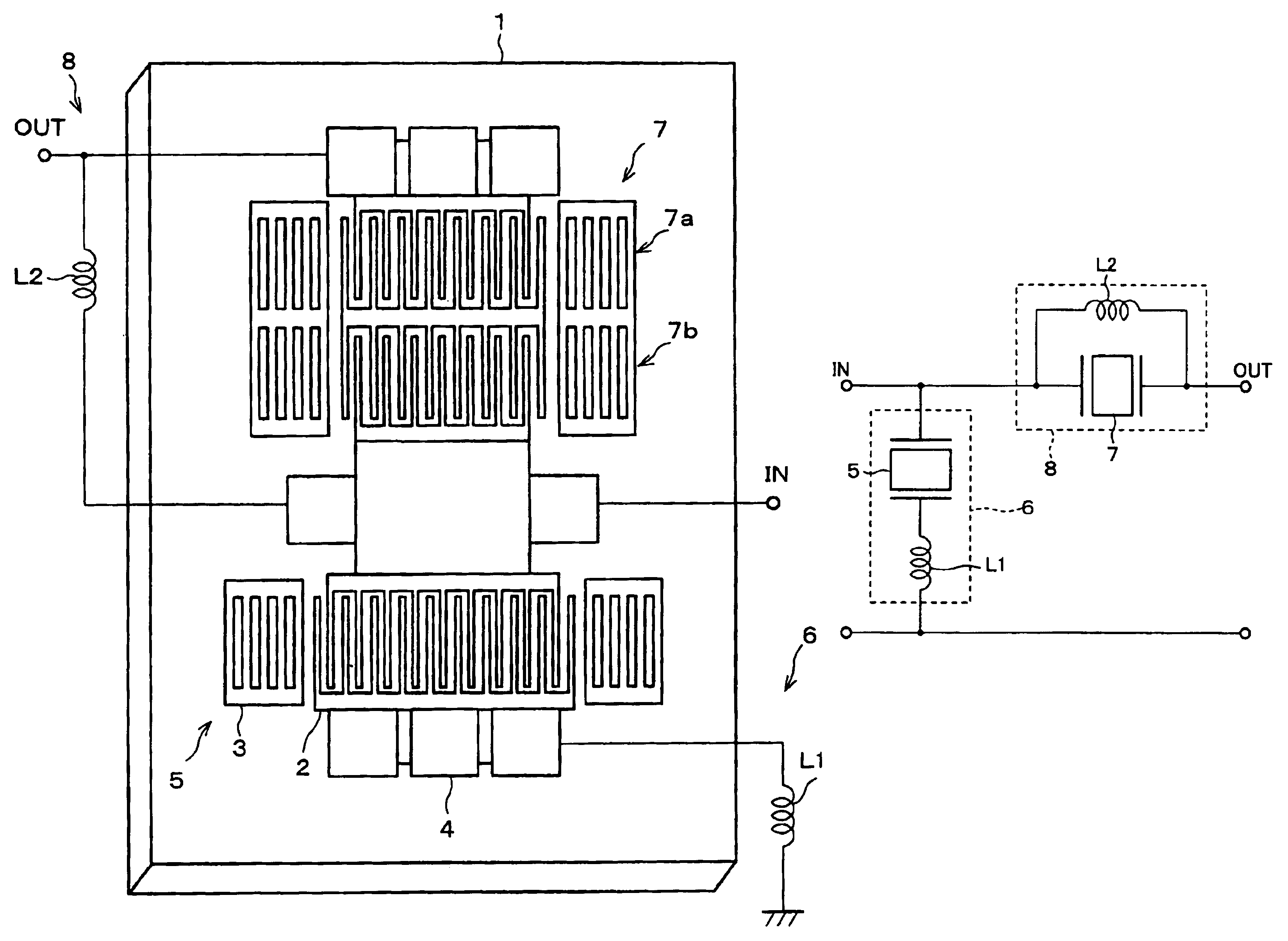
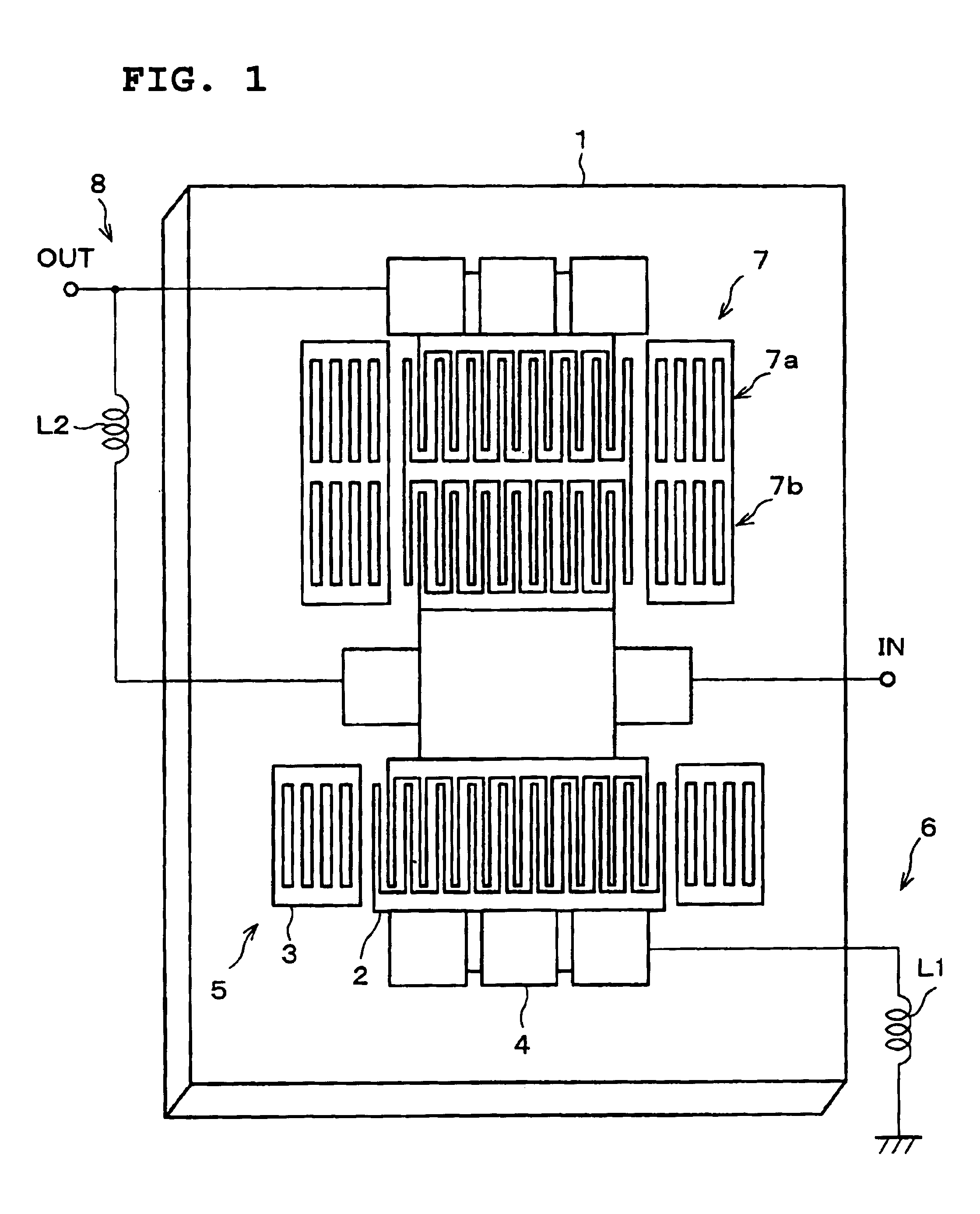
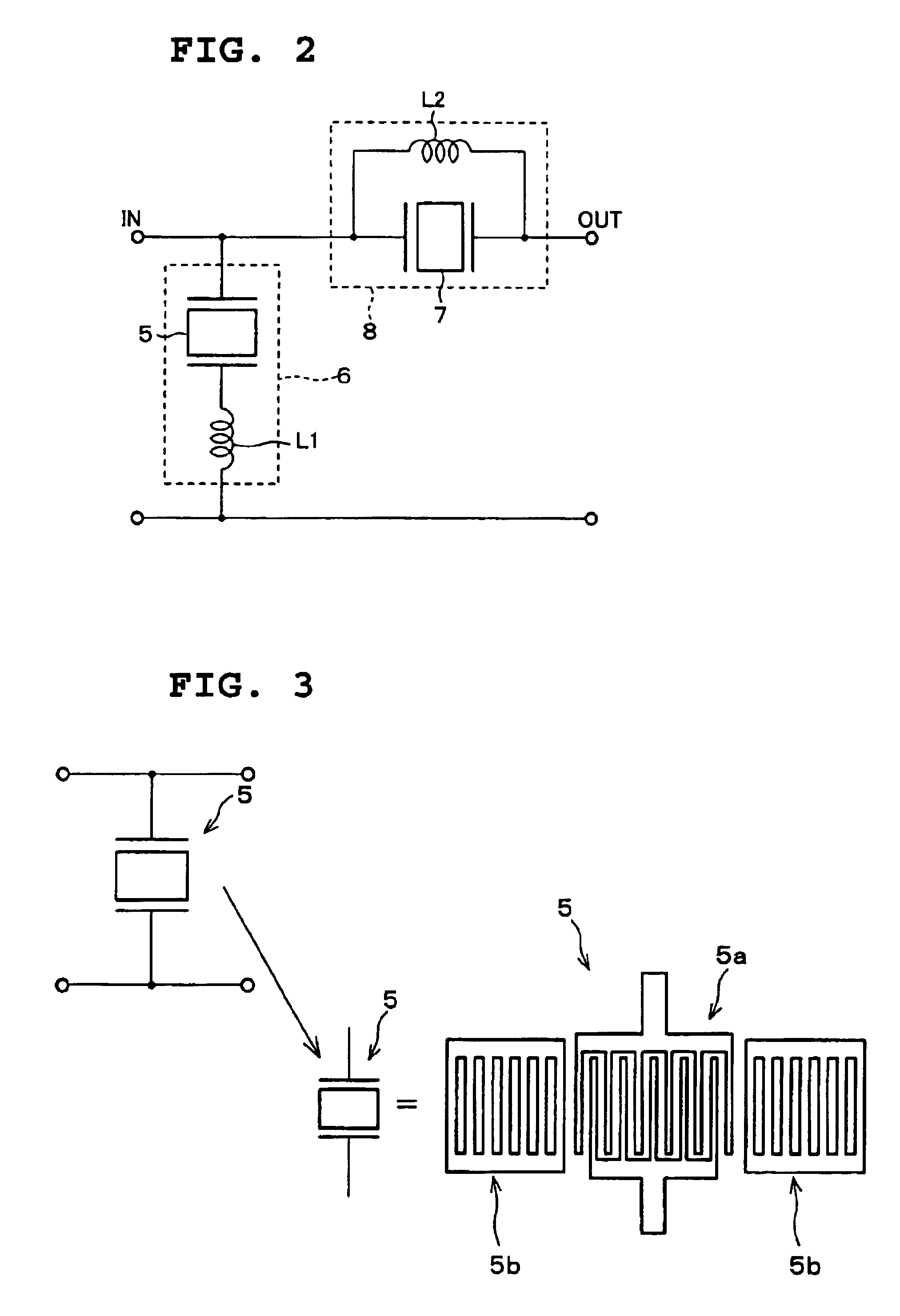
[0097]Hereinafter, an example of a surface acoustic wave filter according to a preferred embodiment of the present invention will be described. FIG. 1 shows an 800 MHz band PDC filter with a central frequency of 949 MHz. FIG. 2 shows a circuit configuration. The surface acoustic wave filter includes a piezoelectric substrate 1, e.g., preferably made of a 41° Y-cut X-propagation LiNbO3 substrate, interdigital electrodes 2 for propagating a surface acoustic wave, reflector electrodes 3, and wire-bonding pads 4 to be electrically connected to electrode terminals of a package by wire-bonding, which are provided on the piezoelectric substrate 1. The interdigital electrodes 2, the reflector electrodes 3, and the wire-bonding pads 4 are provided on a metallic electrode film, e.g., by a photolithographic method. A plurality of interdigital electrodes 2 are provided on the piezoelectric substrate 1 in the surface acoustic wave propagation direction. Thereby, the first and second one terminal...


PUM


Abstract

In a ladder type filter, a first inductor is connected in series with a parallel resonator. A second inductor is connected in parallel to a series resonator. The resonant point of the parallel resonator having the first inductor connected in series and the anti-resonant point of the series resonator developed on the lower frequency side of the resonant point of the series resonator, caused by the second inductor connected in parallel, substantially coincide with each other.

Description

BACKGROUND OF THE INVENTION[0001]1. Field of the Invention[0002]The present invention relates to a ladder-type filter, and in particular, to a ladder type filter for use in mobile communication devices such as automobile telephones, portable telephones and other suitable devices, a branching filter, and a communication device.[0003]2. Description of the Related Art[0004]In recent years, reductions in size and weight of communication devices such as portable telephones have been required, and composite communication devices have been developed. Dielectric filters having superior electrical characteristics and withstand power properties have been used in branching filters and top filters according to known techniques. Recently, surface acoustic wave (SAW) filters having reduced sizes and weights have been more required for the branching filters and the top filters. Especially, for filters which are used on the transmission sides of branching filters, high withstand power properties ha...

Claims


Application Information

Patent Timeline
Patent Type & Authority Patents(United States)
IPC IPC(8): H03H9/00H03H9/58H03H9/54H03H9/60H03H9/64
CPCH03H9/542H03H9/6463H03H9/605
Inventor OMOTE, RYOICHI
Owner MURATA MFG CO LTD
Learn More