Method and apparatus in the drying section of a paper machine or the like

a technology of paper machines and drying sections, applied in drying machines with progressive movements, lighting and heating apparatus, furnaces, etc., can solve the problems of web breakage, web not always disengaged properly, web not being able to follow the wire in a desired way, etc., to achieve easy control of the negative pressure level and increase the negative pressure

Inactive Publication Date: 2005-06-28
VALMET TECH INC
View PDF17 Cites 15 Cited by
  • Summary
  • Abstract
  • Description
  • Claims
  • Application Information

AI Technical Summary

Benefits of technology

The invention is a solution for controlling negative pressure in a blow box. It uses nozzles to generate negative pressure to prevent air from entering the negative pressure region. The nozzles can be simple gap nozzles or resiliently or pivotally mounted ejection nozzles that move away from the wire to prevent damage. The solution also uses surfaces that utilize the Coanda effect to direct air into a desired direction, even outside the negative pressure region. The negative pressure can be further intensified by creating suction in the blow box. The suction can be controlled using common means creating the blow. A net or the like can be used to prevent paper lint from reaching the suction channels. The technical effects of the invention include controllable and efficient negative pressure control, improved air direction control, and prevention of wire damage.

Problems solved by technology

The technical problem addressed in this patent is the need for a method and device to control the negative pressure in the wire pocket of a paper machine during the drying process, specifically in relation to the opening gap between the drying cylinder and the wire. Previous methods have led to disadvantages such as increased energy usage and air leaks, as well as bending and stretching of the wire which impairs its runability. The invention aims to provide a more effective and flexible solution for securing the travel of the wire in the opening gap while avoiding the negative pressure disadvantages.

Method used


Image

  • Method and apparatus in the drying section of a paper machine or the like
  • Method and apparatus in the drying section of a paper machine or the like
  • Method and apparatus in the drying section of a paper machine or the like

Examples


Embodiment Construction

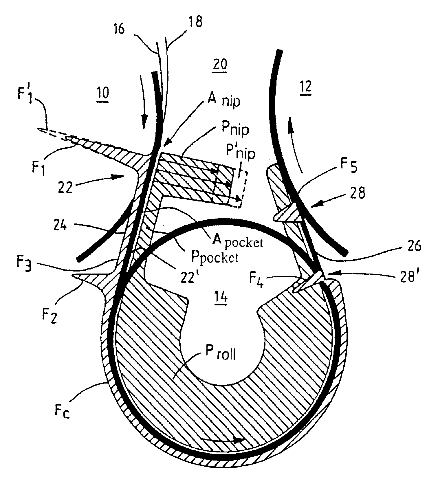
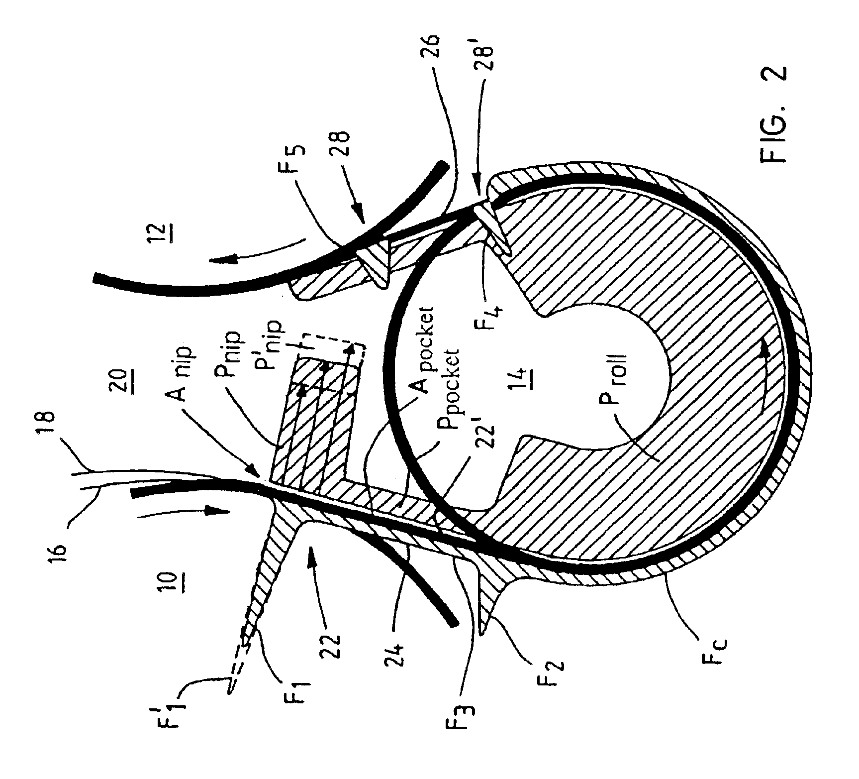
[0090]FIG. 2 shows a schematic drawing of the forces F acting on the web, and of the negative pressures p compensating for these forces in the pocket 20 formed between the two drying cylinders 10, 12, the turn roll 14, the web 16 and the wire 18. In the case of FIG. 2 the turn roll can be e.g. a perforated or grooved suction roll, in which the negative pressure is provided via the axis at the end of the roll. The negative pressure can be provided in the turn roll also via the peripheral sector adjacent to the pocket space. The turn roll can have a smooth surface or a grooved surface. The paper web 16 runs in a winding manner supported by the wire 18, alternately over a cylinder 10, 12 and alternately over a turn roll 14, so that it forms a pocket 20 between the cylinders and the turn roll.

[0091]The wire 18 is disengaged from the periphery of the first cylinder 10 in the so called opening nip 22 and runs to the turn roll 14 so that it forms a so called input wire run 24 between the f...


PUM


Abstract

A web (16) running from an opening nip (K1) between a cylinder (10) and a supporting fabric (18) toward a roll (14), is supported by a negative pressure created by a blow box (30). In an intensified negative pressure region (34′), i.e. close to the disengaging point (40) between the supporting fabric and the cylinder, the pressure is greater than at a distance from this disengaging point. The negative pressure is controlled according to parameters which act on the runability of the web and which can be varied, such as web velocity, web solid contents, pulp composition, paper or paper board quality, web grammage, a characteristic of the web, such as porosity, traction acting in the web, or web tension, cylinder temperature, and/or the running situation, such as a web break, a threading situation, or a normal run, so the desired runability is maintained between the cylinder and the roll.

Description


Claims


Application Information

Patent Timeline
Owner VALMET TECH INC
Why Eureka
Try Eureka