Cage spacer

Inactive Publication Date: 2005-06-28
FORTERRA CONCRETE PROD INC
View PDF17 Cites 13 Cited by
  • Summary
  • Abstract
  • Description
  • Claims
  • Application Information

AI Technical Summary

Benefits of technology

[0009]The pyramid spacers have a pointed tip for contacting the mold walls thus leaving a small footprint on the outer portion of the poured concrete. The pyramid spacers also have a wide base with the clips spaced at the ends of the base for engaging rebars or welded fabric to provide stability against twisting forces such that the pyramid spacer remains oriented to space the rebars or welded fabric at a specified distance from the mold walls. Further the clips on the pyramid spacers have a rebar engaging portion for the rebar or welded fabric to fit into and two arms pressing on the rebar or welded fabric to lock the rebar or welded fabric snugly in place. The pyramid spacers also have a pair of pads at the corners of the base for engaging a perpendicularly crossing rebar or welded fabric to stably hold the pyramid spacers in a plane defined by the intersection of the rebars or welded fabric. Having only one pair of clips makes it easier to install the pyramid spacers.
[0010]In another embodiment the cage spacers have a trapezoid body portion and a double apex body portion with pads and clips for engaging the rebars or welded fabric. The double apex embodiment provides more stability of the cage spacer relative to the mold wall by having two contact points. In a further embodiment the cage spacer has two perpendicular double apex portions providing four apexes for engaging the mold wall and defining the plane of contact such that the cage spacer is stable on all axis against the mold wall.OBJECTS OF THE INVENTION

Problems solved by technology

In this use a large contact area with the wall will leave a large area of the spacer exposed when the mold is removed.
These spacers are thus not held sufficiently straight, resulting in variations of spacing distance between the mold wall and the rebars or welded fabric.
Some spacers have clip on connections, which can come loose during impacts received during the construction process.

Method used


Image

  • Cage spacer
  • Cage spacer
  • Cage spacer

Examples


Embodiment Construction

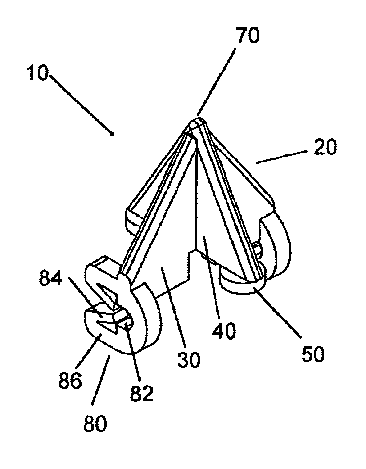
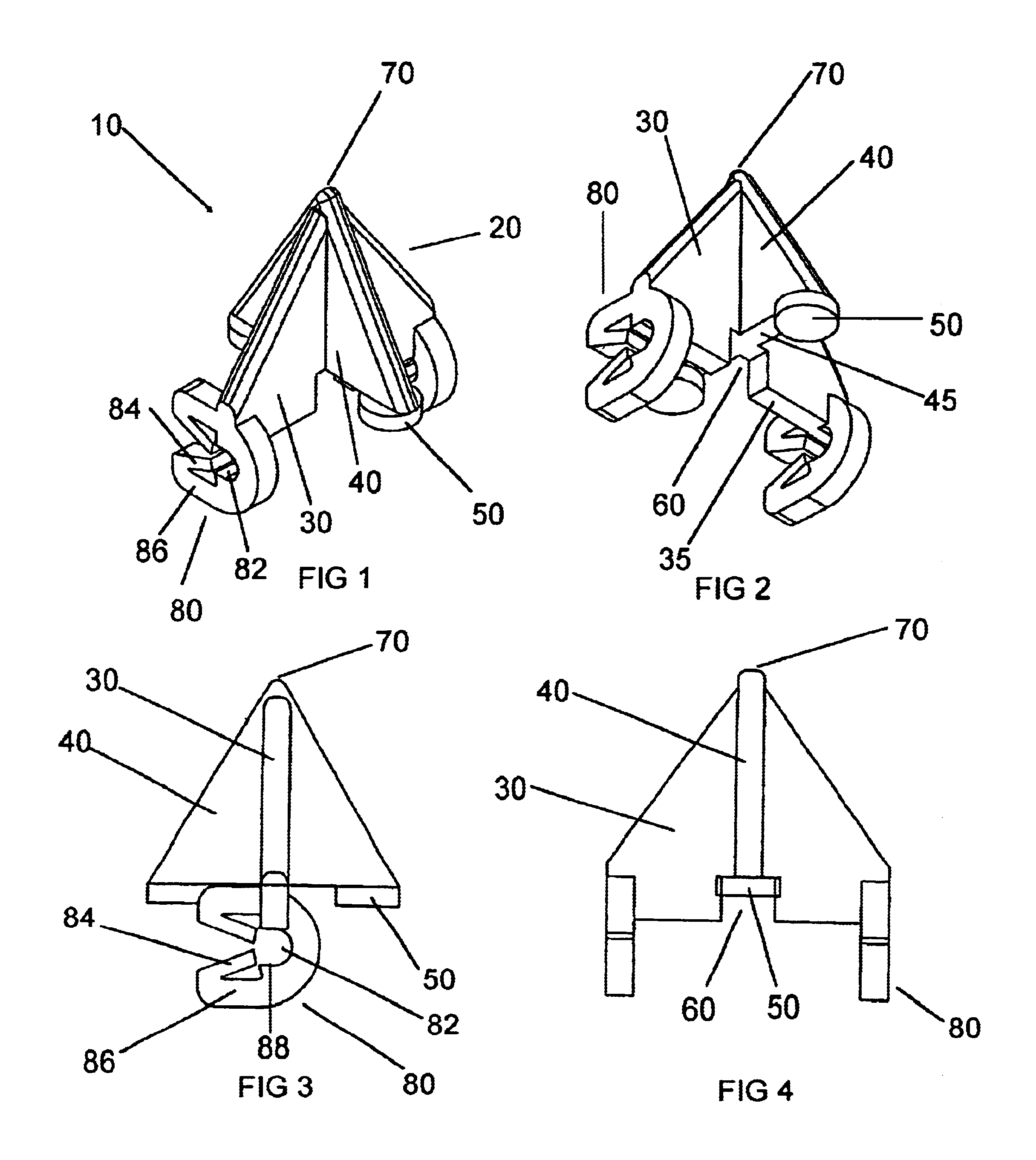
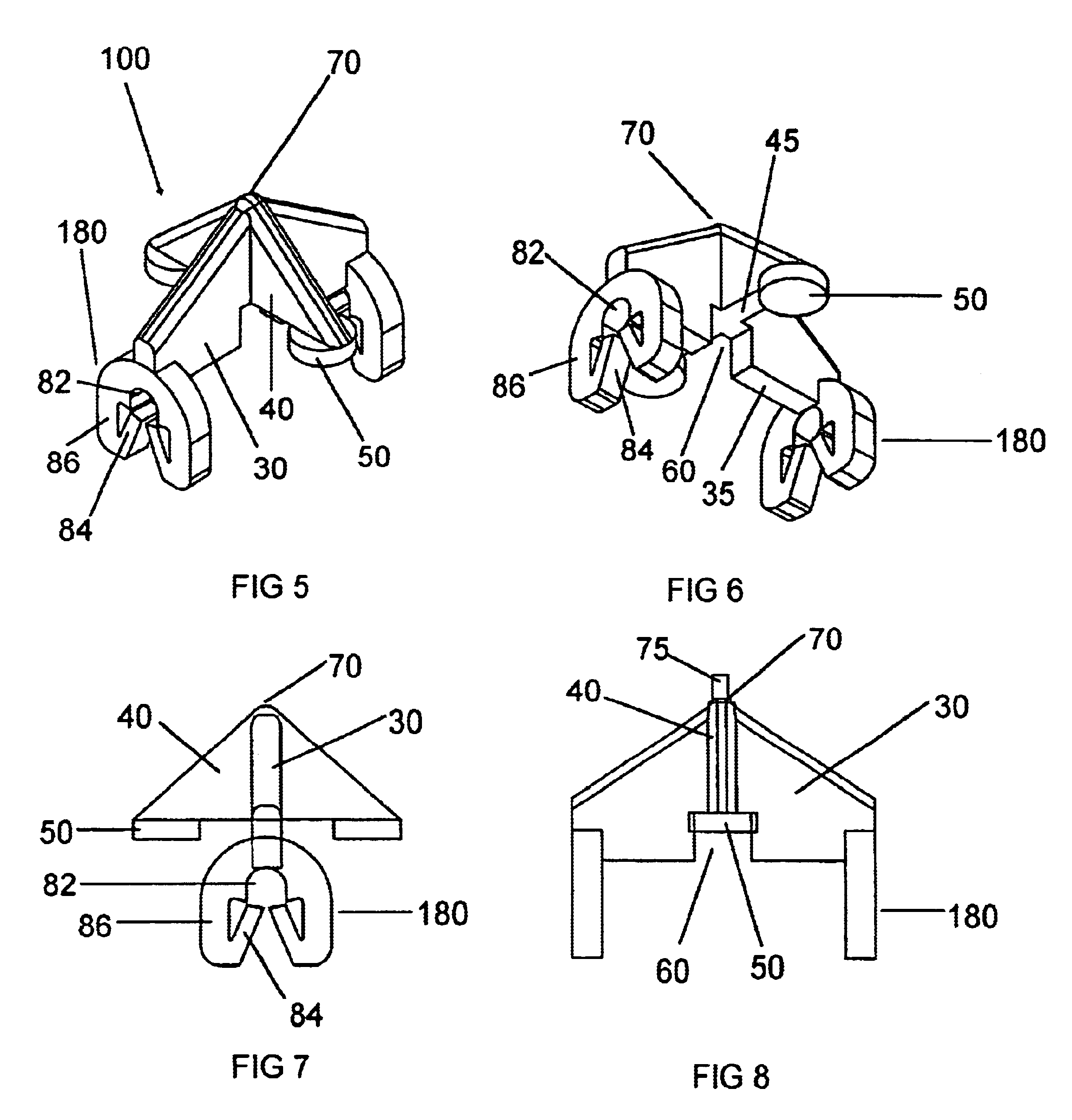
[0032]There are two cage spacer clip orientations shown in the figures. In FIGS. 1-4 the cage spacer 10 has a sideways facing clip portion 80 for engaging a reinforcing rod. In a second embodiment, shown in FIGS. 5-8, the cage spacer 100 has a downward facing clip portion 180 for engaging a reinforcing rod. In all other respects the structure of cage spacers 10 and 100 are the same in the two embodiments.

[0033]The cage spacer 10 has a pyramid portion 20 comprising two triangle body portions 30 and 40, intersecting right angles to each other and overlapping in their center portions along a common central apex axis. The triangles 30 and 40 are offset at their tips and bases such that the top of triangle portion 40 is the tip of apex 70. The tip of triangle 30 is slightly lower than the tip of triangle 40. The footprint of the apex 70 of the cage spacer 10 is thus reduced at the interface with the mold thus increasing the concrete available at the mold surface. The base 35 of triangle ...


PUM

PropertyMeasurementUnit
Distanceaaaaaaaaaa
Circumferenceaaaaaaaaaa

Abstract

A cage spacer for spacing reinforcing rods or welded fabric a specified distance from mold walls for poring concrete during construction projects. The cage spacer comprises two intersection bodies oriented perpendicular to each other and preferable with one body having a base higher than the other. A pair of pads on opposite ends of a first body base for stabilizing the body on the rebar. A pair of rebar engaging clips on opposite ends of the second body base for snapping onto and gripping a perpendicularly intersecting rebar such that the rebar is held securely in the clips. The cage spacer attaches over the intersection of a pair of rebars. At least one apex of the bodies engages a mold wall to keep the mold wall a specified distance from the rebars while concrete is being poured in the mold.

Description

[0001]This is a continuation-in-part of Ser. No. 10 / 304,774 filed Nov. 26, 2002, now U.S. Pat. No. 6,758,021 which is a continuation-in-part of Ser. No. 10 / 224,837 filed Aug. 21, 2002.BACKGROUND OF THE INVENTION[0002]1. Field of the Invention[0003]This invention relates to clip on spacers for rebars or welded fabric used in structures to space the rebars or welded fabric a specified distance from concrete mold walls.[0004]2. Description of the Related Art[0005]In the past concrete rebars or welded fabric have been held in place by a variety of devices. Some of the devices are for holding the rebars or welded fabric a specified distance above the ground and so have a large ground contacting area to form a stable base for holding the rebars or welded fabric up without the spacer tipping over. Other spacers are used to hold mold walls away from a lattice of intersecting rebars or welded fabric. In this use a large contact area with the wall will leave a large area of the spacer exposed...

Claims


Application Information

Patent Timeline
IPC IPC(8): E04C5/20
CPCE04C5/20
Inventor TRANGSRUD, JULIAN P.
Owner FORTERRA CONCRETE PROD INC
Why Eureka
Try Eureka