Mounting Arrangement for Mounting Cooler Unit to Work Machine

Active Publication Date: 2010-09-16
KUBOTA LTD
View PDF6 Cites 4 Cited by
  • Summary
  • Abstract
  • Description
  • Claims
  • Application Information

AI Technical Summary

Benefits of technology

[0007]In view of the above-described drawback of the conventional art, the principal object of the present invention is to provide a mounting arrangement for mounting a cooler unit to a work machine, which arrangement allows maintenance operation of the cooler unit and / or the engine to be effected smoothly.
[0012]Especially, if the general construction of an engine room of the work machine is taken into consideration, it is advantageous to allow the cooler unit to effect a horizontal movement in order to change the distance relative to the engine effectively.
[0013]If the cooler unit effects a translational movement, or preferably a horizontal movement by the function of the movement mechanism so as to increase the distance relative to the engine, there is created a space between the cooler unit and the engine, and this space facilitates maintenance operations of the cooler unit and / or the engine, in particular the troublesome maintenance of their mutually opposed sides.
[0014]According to one preferred embodiment, the mounting arrangement further comprises a tilt mechanism provided between the cooler unit and the support deck, the tilt mechanism allowing tilting of an upper portion of the cooler unit in the direction away from the engine after the horizontal movement of this cooler unit away from the engine. By the function of the movement mechanism, the cooler unit is moved in the direction away from the engine and then by the function of the tilt mechanism, the upper portion of the cooler unit is tilted about the lower portion thereof, in the direction away from the engine. With these movements, there is created larger upper space with greater opening width between the engine and the cooler unit. Further, if the movement mechanism and the tilt mechanism are combined together as an integral movement / tilt mechanism, then, due to shared use of members, there is achieved advantage of greater simplicity of the construction.

Problems solved by technology

With the above-described conventional art, since the radiator is pivoted about its lower portion relative to the frame while the radiator is located at is mounted position, it is difficult to form a space for maintenance between the lower portion of the radiator and the engine.

Method used


Image

  • Mounting Arrangement for Mounting Cooler Unit to Work Machine
  • Mounting Arrangement for Mounting Cooler Unit to Work Machine
  • Mounting Arrangement for Mounting Cooler Unit to Work Machine

Examples


second embodiment

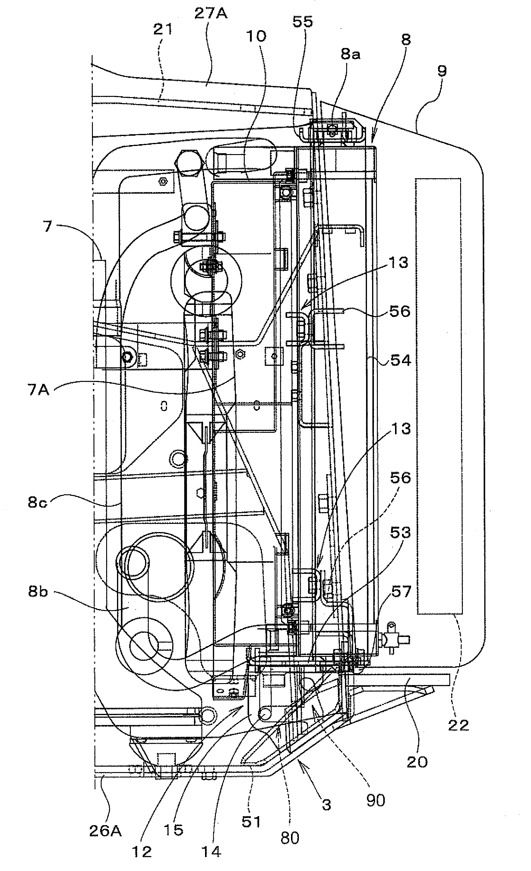
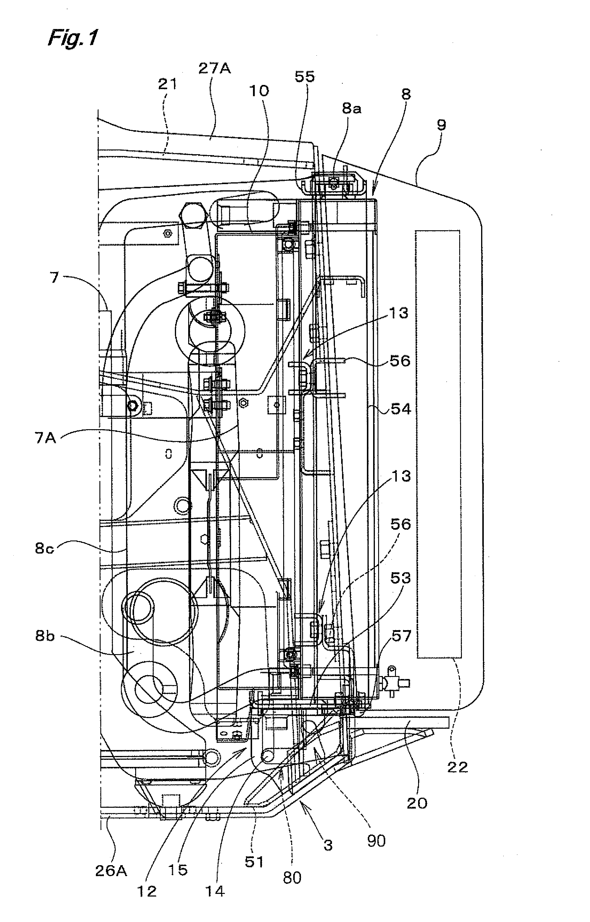
[0093]FIGS. 14 through 19 show a second embodiment of the present invention. In this second embodiment, the movement mechanism 80 and the tilt mechanism 90 for the cooler unit 8 are formed in a horizontal plate.

[0094]A cooler unit frame 8B includes a lower plate 53, a pair of right and left side plates 64, and an upper plate 55. In the lower face of the lower plate 53, there is provided a hook member 17 as a downward projection, the hook member being formed by inserting and fixing a pin through right and left sides of a front portion. And, at a lower end of this hook member 17, there is engaged and fixedly attached, under an inclined posture, a stopper member 18 having an approximate front-round, rear-rectangular shape.

[0095]Each one of the pair of right and left support decks 12 fixed to the extension bottom plate 51 is formed by bending a band plate into a portal shape and its upper face forms a horizontal portion capable of mounting thereon the cooler unit 8, and this horizontal ...

third embodiment

[0112]A cooler unit mounting arrangement according to a third embodiment of the invention will be described next with reference to FIG. 24, FIG. 25 and FIGS. 26A, B, C. The cooler unit mounting arrangement relating to this third embodiment largely differs from the foregoing embodiments in the following two respects.

[0113](1) The engaging members 14 are provided with downward orientation at opposed end portions of the lower plate 53 of the cooler unit frame 8B. The positioning member 58 is fixed to the lower face of the lower plate 53 at its substantially right / left center. In this embodiment, this positioning member 58 is provided as a downwardly oriented projecting member bent in the U-shape. As the positioning member 58 is engaged in a through hole 3a defined in a floor plate 3A constituting the machine body frame 3, the positioning of the cooler unit 8 is realized.

[0114](2) The slots such as the movement slot 81 and the tilt slot 91 formed in the guide vertical plate 15 so as to ...


PUM


Abstract

A mounting arrangement for mounting a cooler unit to a work machine has a traveling device, a machine body frame, an engine and the cooler unit disposed adjacent the engine. The arrangement includes a support deck provided in the machine body frame for supporting the cooler unit, an attachment unit for releasably fixing the cooler unit to the machine body frame and a movement mechanism provided between the cooler unit and the support deck, the movement mechanism allowing the cooler unit to effect a translational movement to change a distance relative to the engine.

Description

BACKGROUND OF THE INVENTION[0001]1. Field of the Invention[0002]The present invention relates to a mounting arrangement for mounting a cooler unit to a work machine including a traveling device, a machine body frame, an engine and the cooler unit disposed adjacent the engine.[0003]2. Description of the Related Art[0004]With this type of work machine, as disclosed in Japanese Patent Application “Kokai” No. 2002-294748, there is provided a first connecting means connected to an engine of the work machine, the first connecting means pivotally attaching a radiator connected to the engine to the frame so that the radiator may be pivoted about its lower edge, from its closed position where the radiator is located near the frame and its opened position where the radiator is located by a certain distance from the frame. This first connecting means includes a plurality of support members completely fixed to the frame in respective correspondence with the lower edge of the radiator. Each one ...

Claims


Application Information

Patent Timeline
IPC IPC(8): F28F9/007F28D15/00
CPCF28F9/002B60K11/00F28F2280/10E02F9/0808
Inventor KOTANI, SHINSUKEFUJINO, MASANORIMITSUI, KENJIYASUDA, TOYOAKI
Owner KUBOTA LTD
Why Eureka
Try Eureka