Rotation transmission device

Inactive Publication Date: 2008-03-13
NTN CORP
View PDF2 Cites 6 Cited by
  • Summary
  • Abstract
  • Description
  • Claims
  • Application Information

AI Technical Summary

Benefits of technology

[0007]In order to achieve this object, the present invention provides a rotation transmission device comprising an inner ring having an outer periphery, an outer ring having an inner periphery, one of the outer periphery and inner periphery being formed with cam surfaces, and the other of the outer periphery and inner periphery being formed with a cylindrical surface, a plurality of pairs of rollers, each pair being disposed between one of the cam surfaces and the cylindrical surface to circumferentially face each other, roller separation springs each disposed between one of the plurality of pairs of rollers to bias the pair of rollers away from each other until wedged between the one of the cam surfaces and the cylindrical surface, and a roller retainer retaining the rollers and capable of changing the distance between each of the plurality of pairs of rollers, whereby the rollers are disengageable from the cam surfaces and the cylindrical surface by reducing the circumferential distance between each of the plurality of pairs of rollers with the roller retainer.
[0010]1) The rotation transmission device further comprises stoppers each disposed between one of the plurality of pairs of rollers for restricting the minimum distance between the pair of rollers, thereby preventing breakage of the roller separation springs.

Problems solved by technology

Thus, a delay in response necessarily occurs because the roller retainer has to be moved to change the direction of rotation.
Thus, it may be difficult to sufficiently quickly change the direction of rotation.
If the distance by which the roller retainer has to be moved to change the direction of rotation is reduced in an attempt to improve the response of changes in the direction of rotation, the rollers are more likely to be untimely wedged between the cam surfaces and the cylindrical surface, so that the reliability in operation deteriorates.

Method used


Image

  • Rotation transmission device
  • Rotation transmission device
  • Rotation transmission device

Examples


first embodiment

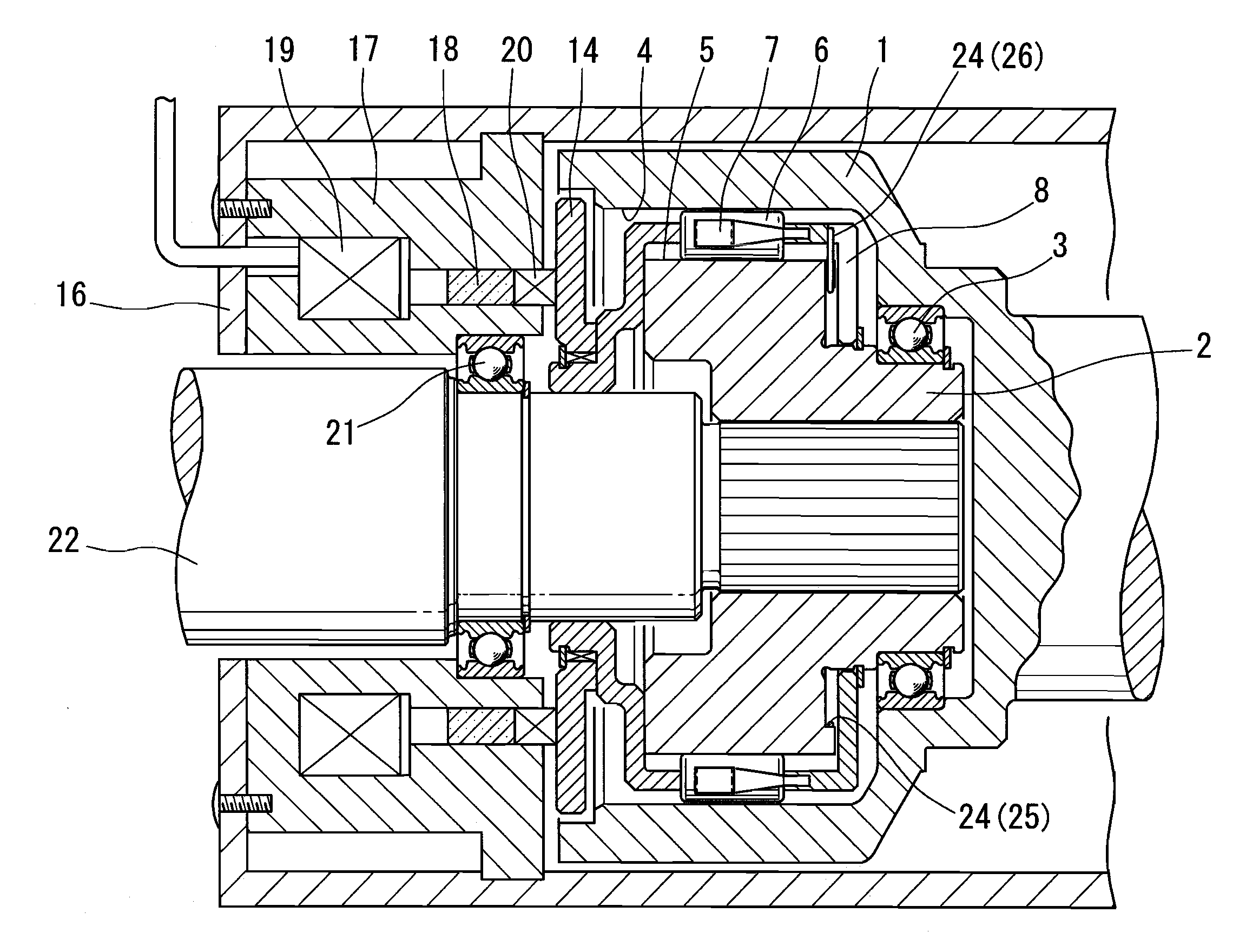
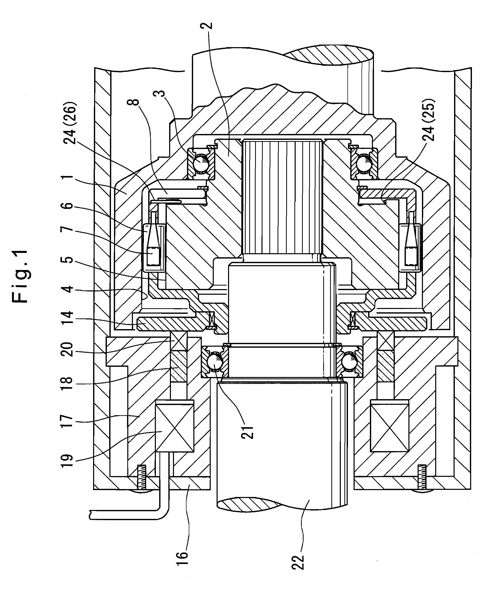
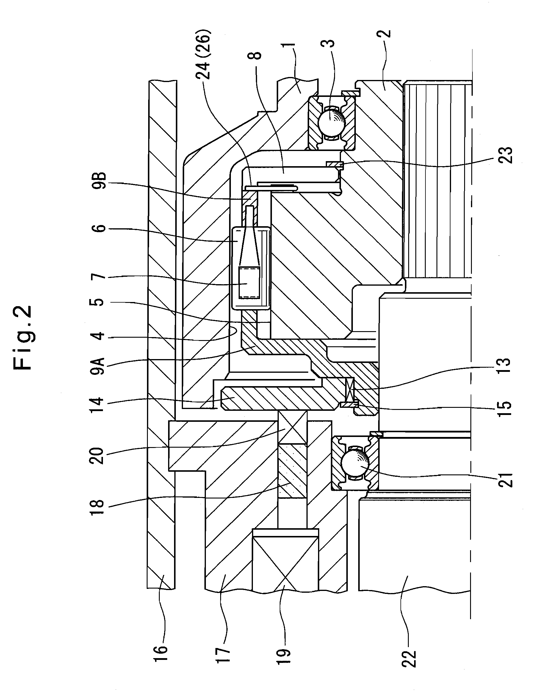
[0053]Now referring to FIGS. 1 to 5, the rotation transmission device of the first embodiment includes, as shown in FIGS. 1 and 2, an inner ring 2 and an outer ring 1 which is rotatably supported on the inner ring 2 through a rolling bearing 3 provided around the inner ring 2. As shown in FIG. 4, a cylindrical surface 4 is formed on the inner periphery of the outer ring 1, and cam surfaces 5 are formed on the outer periphery of the inner ring 2 to define wedge spaces in cooperation with the cylindrical surface 4. Each wedge space has a radial width that gradually decreases from its circumferential central portion to circumferential ends.

[0054]As shown in FIGS. 3 and 4, a pair of circumferentially opposed rollers 6 are disposed between each cam surface 5 and the cylindrical surface 4. A roller separation spring 7 is disposed between the pair of rollers 6 to bias the rollers 6 circumferentially away from each other. A roller retainer 8 keeps constant the distance between each pair of ...

third embodiment

[0087]The operation of this rotation transmission device is now described. When the electromagnetic coil 53 is deenergized, the armature 50 is magnetically attracted by the permanent magnet 52 until it abuts the rotor 51, so that the annular retainer member 9A is moved away from the annular retainer member 9B. Thus, as in the third embodiment, each pair of rollers 6 are both wedged between the cam surface 5 and the cylindrical surface 4.

[0088]When the electromagnetic coil 53 is energized, the annular retainer member 9A is moved toward the annular retainer member 9B under the force of the armature separation spring 55. Thus, as in the third embodiment, each pair of rollers 6 both disengage from the cam surface 5 and the cylindrical surface 4.

[0089]In this embodiment too, as in the first embodiment, with both of each pair of circumferentially opposed rollers 6 wedged between the cam surface 5 and the cylindrical surface 4 by increasing the distance therebetween, it is possible to tran...


PUM


Abstract

A rotation transmission device which can quickly change the direction of rotation. It includes a inner ring formed with cam surfaces on its outer periphery, a outer ring formed with a cylindrical surface on its inner periphery, and a plurality of pairs of rollers, each pair being disposed between one of the cam surfaces and the cylindrical surface so as to be circumferentially opposed to each other. A roller separation spring is disposed between each pair of rollers to bias the rollers away from each other so that the rollers are wedged between the cam surface and the cylindrical surface. The rollers are retained by a roller retainer which can change the distance between each pair of circumferentially opposed rollers. By reducing the distance between each pair of rollers with the roller retainer, it is possible to disengage the rollers from the cam surfaces and the cylindrical surface.

Description

BACKGROUND OF THE INVENTION[0001]This invention relates to a rotation transmission device used for selectively transmitting power through a power transmission line.[0002]Conventional rotation transmission devices for selectively transmitting power typically include an inner ring and an outer ring, with cam surfaces and a cylindrical surface formed on one and the other of the outer periphery of the inner ring and the inner periphery of the outer ring, respectively, a plurality of pairs of rollers, each pair being disposed between the cylindrical surface and one of the cam surfaces and circumferentially opposed to each other, and a roller retainer for maintaining the distance between each pair of circumferentially opposed rollers. The roller retainer is circumferentially movable between a position where the rollers are wedged between the cam surfaces and the cylindrical surface and a position where the rollers are disengaged from the cam surfaces and the cylindrical surface.[0003]In t...

Claims


Application Information

Patent Timeline
IPC IPC(8): F16D27/02
CPCF16D41/105
Inventor SAITO, TAKAHIDEAKIYOSHI, KOJISATO, TAKANOBUASHIMORI, MASAKO
Owner NTN CORP
Why Eureka
Try Eureka