
Adjustable wrench

Inactive Publication Date: 2006-02-09
RHODES ROBERT V
View PDF7 Cites 8 Cited by
  • Summary
  • Abstract
  • Description
  • Claims
  • Application Information

AI Technical Summary

Benefits of technology

[0007] It is an object of the present invention to provide an adjustable rack type crescent wrench that allows the user to quickly and easily change the distance between the jaws of the wrench and then to automatically engage a nut or bolt head when the wrench is in position. This objective is achieved through the design of an internal spring type mechanism that is engineered and designed to engage one end of the moveable jaw assembly so that when the jaw is extended into the open position, it can then be released by the user pressing down on an operator mechanism that releases the worm gear from the rack of the movable jaw which instantly adjusts the distance between the jaws in a manner to securely grasp the flat portions of a nut, bolt head or like fastener.
[0008] Another objective of the invention is to provide an adjustable wrench of the aforementioned character that is easy to use and reliable in operation.
[0009] Another object of the invention, is to provide an adjustable wrench as described in the preceding paragraphs that is of a simple design and one that can be inexpensively manufactured.

Problems solved by technology

In the operation of a conventional “worm gear” adjustable wrench, there is a tendency for the movable jaw portion of the wrench to loosen during the process of the tightening or loosening of the nut or bolt head.
The disadvantage inherent in this procedure, however, is that it takes two hands to accomplish the adjustment of the moveable jaw, one hand to hold the wrench and the other hand to manually adjust the moveable jaw to the desired distance between the jaws and then to close the jaw against the nut or bolt head.
This can be a drawback where a one-handed jaw closing operation is desired, needed or required.
For example, if a person is reaching behind a machine where there is a wall in close proximity to the back of the machine, or on other equipment where working space is too tight or at a premium, the user may not have room to reach in with the other hand to move the adjustable jaw into position against the nut or bolt head.

Method used


Image

  • Adjustable wrench
  • Adjustable wrench
  • Adjustable wrench

Examples


Embodiment Construction

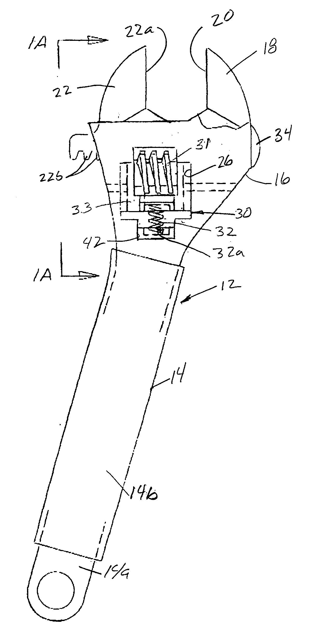
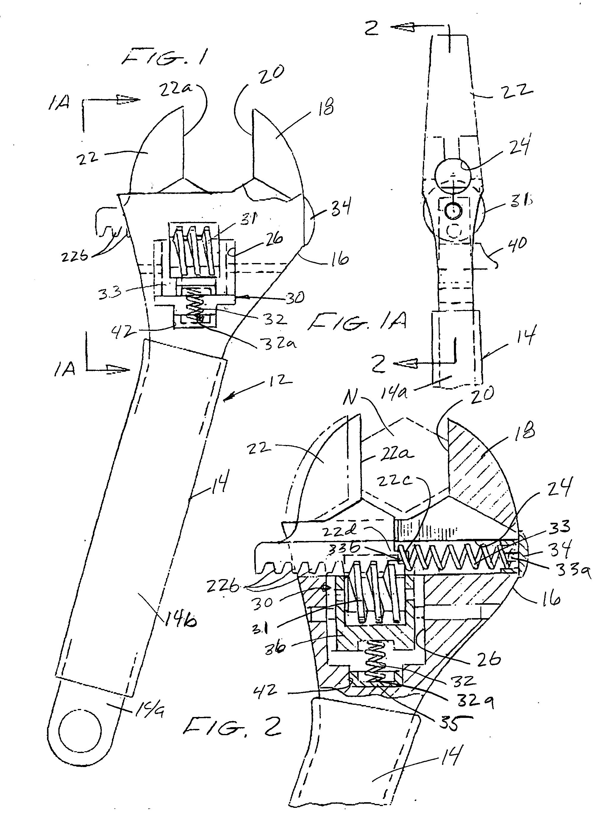
[0017] Referring to the drawings and particularly to FIGS. 1 through 3, one form of the adjustable wrench of the present invention is there illustrated. As best seen in FIG. 1, the adjustable wrench here comprises a body 12 which includes an elongate handle portion 14 and a head portion 16. Head portion 16 includes a fixed jaw 18 having a grasping face 20 and a movable jaw 22. As shown in FIG. 2, head portion 16 is provided with a transverse bore 24 and a generally vertically extending chamber 26 that is disposed proximate the transverse bore.

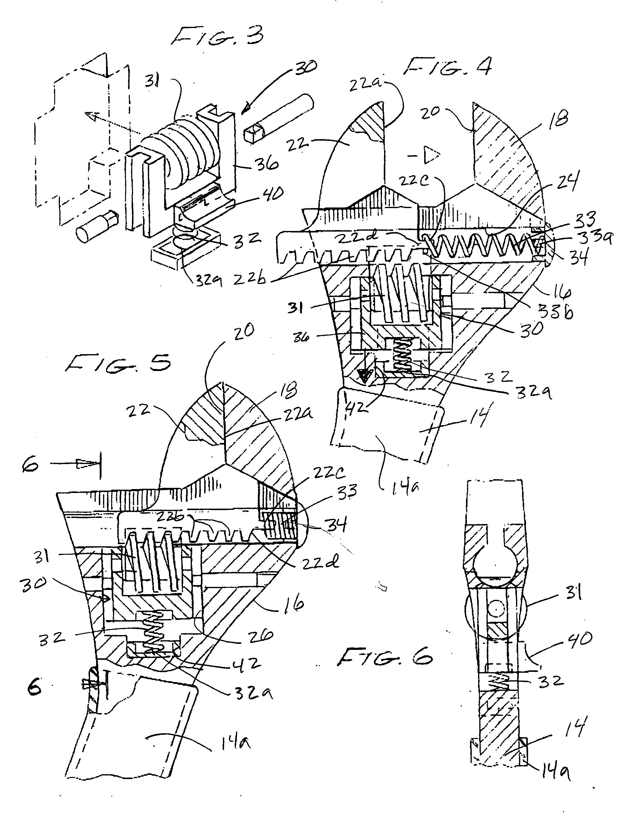
[0018] Mounted within chamber 26 is an operator assemblage 30 (FIG. 3) which is slidably movable within the cavity between the first operating position shown in FIG. 2 and the second, retracted position shown in FIG. 4. An operator assemblage biasing means, shown here as a coil spring 32, is carried by head portion 16 for continuously biasing the operator assemblage 30 toward the first operating position.

[0019] As illustrated in FIGS. 2, 4 an...


PUM


Abstract

An adjustable rack type crescent wrench that allows the user to quickly and easily change the distance between the jaws of the wrench and then to automatically engage a nut or bolt head when the wrench is in position. The wrench includes an internal spring type mechanism that is engineered and designed to engage one end of the movable jaw assembly so that when the jaw is extended into the open position, it can then be released by the user pressing down on an operator mechanism that releases the worm gear from the rack of the movable jaw which instantly adjusts the distance between the jaws in a manner to securely grasp the flat portions of a nut bolt head or like fastener, while still allowing final, slight, adjustments to the position of the jaws by virtue of the ability to manipulate the sliding jaw with the worm gear.

Description

BACKGROUND OF THE INVENTION [0001] 1. Field of the Invention [0002] The invention relates generally to the field of wrenches and more specifically to an adjustable crescent type wrench. Crescent wrenches are well known. They generally come in sets from small to large so that the user can select the proper wrench for the nut that is to be tightened or loosened. [0003] 2. Discussion of Prior Art [0004] Standard adjustable crescent wrenches include an adjustable jaw that can be positioned in or out with respect to a fixed jaw when the user turns a “worm type gear” that is engaged with a rack portion located on a horizontal sliding member that is integral with the adjustable jaw of the wrench. These type of wrenches are helpful in that one wrench can take the place of an entire set of standard open ended wrenches. In the operation of a conventional “worm gear” adjustable wrench, there is a tendency for the movable jaw portion of the wrench to loosen during the process of the tightening ...

Claims


Application Information

Patent Timeline
IPC IPC(8): B25B13/16
CPCB25B13/14
Inventor RHODES, ROBERT V.
Owner RHODES ROBERT V
Learn More