Cable-stripping pliers

Active Publication Date: 2005-06-28
PRESSMASTER
View PDF11 Cites 35 Cited by
  • Summary
  • Abstract
  • Description
  • Claims
  • Application Information

AI Technical Summary

Benefits of technology

[0004]It is difficult to replace the cutting devices or cutting unit in previously known cable-stripping pliers. Conseque

Problems solved by technology

It is difficult to replace the cutting devices or cut

Method used


Image

  • Cable-stripping pliers
  • Cable-stripping pliers
  • Cable-stripping pliers

Examples


Embodiment Construction

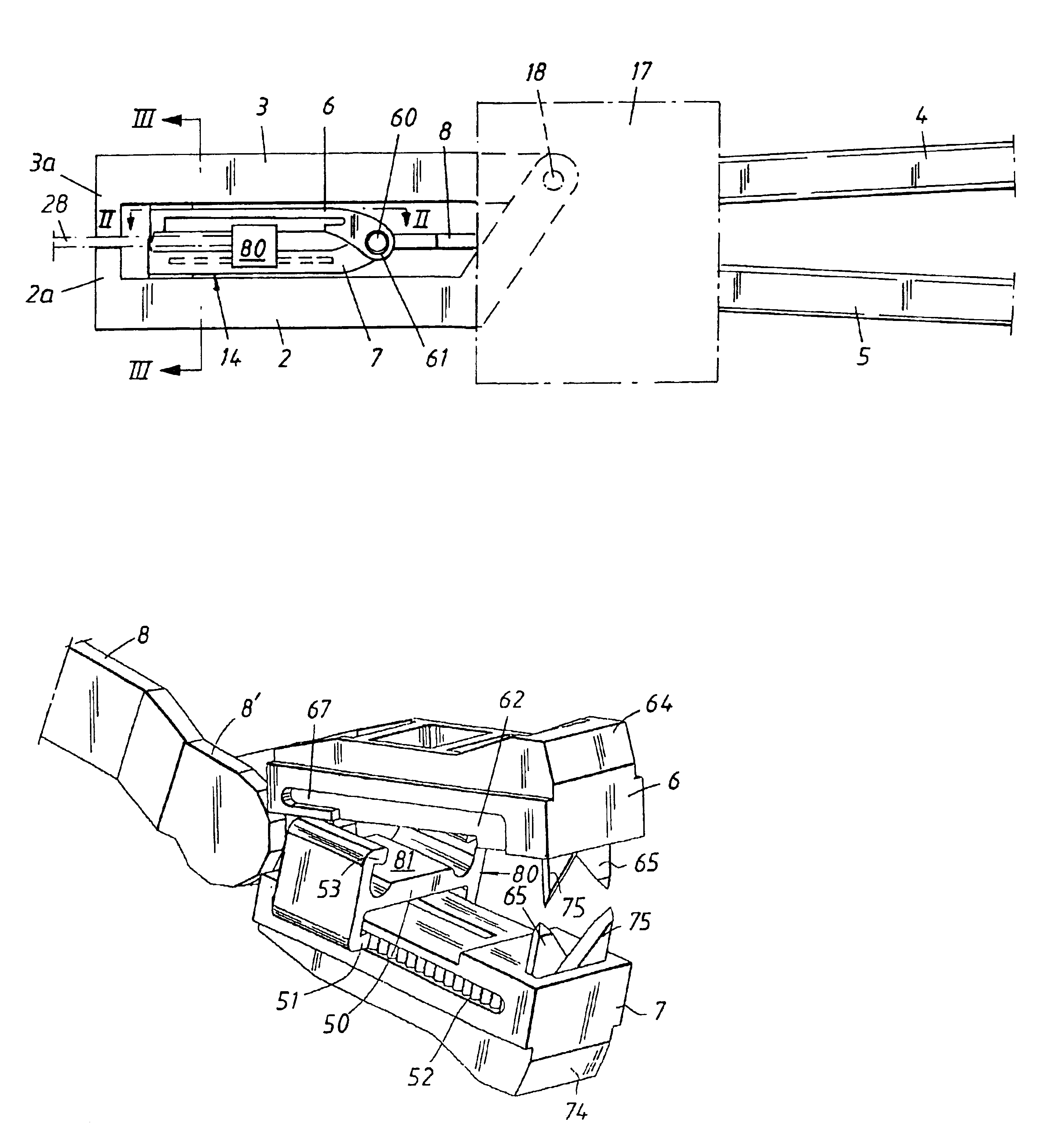
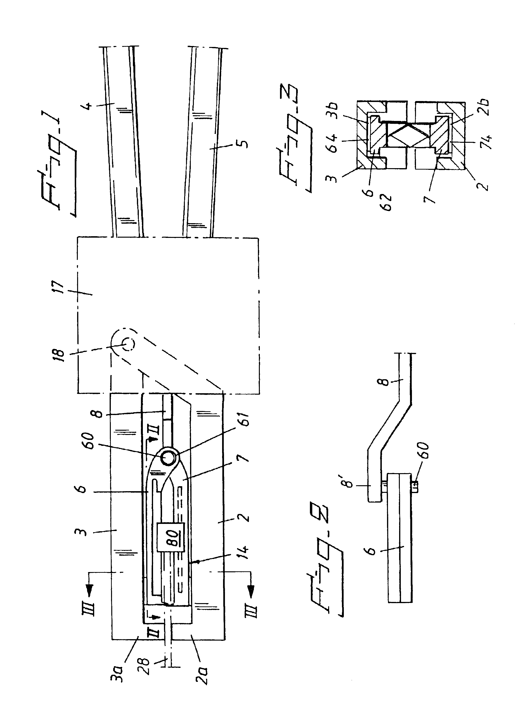
[0016]FIG. 1 illustrates schematically cable or wire stripping pliers that include mutually pivotal handgrip legs 4, 5 which, through the medium of a pliers mechanism 17, are coupled to mutually pivotal clamping jaws 2, 3 which carry at their free ends clamping elements 2a, 3a for gripping a cable 28 to be stripped. A cutting unit 14 is located between the jaws 2, 3. The cutting unit includes a tubular pivot mounting 61 whose axis extends normal to a plane which is “tented” by the pivotal movement of the jaws 2, 3.

[0017]The clamping jaws 2, 3 can be considered to be pivotally mounted relative to one another about an axis 18.

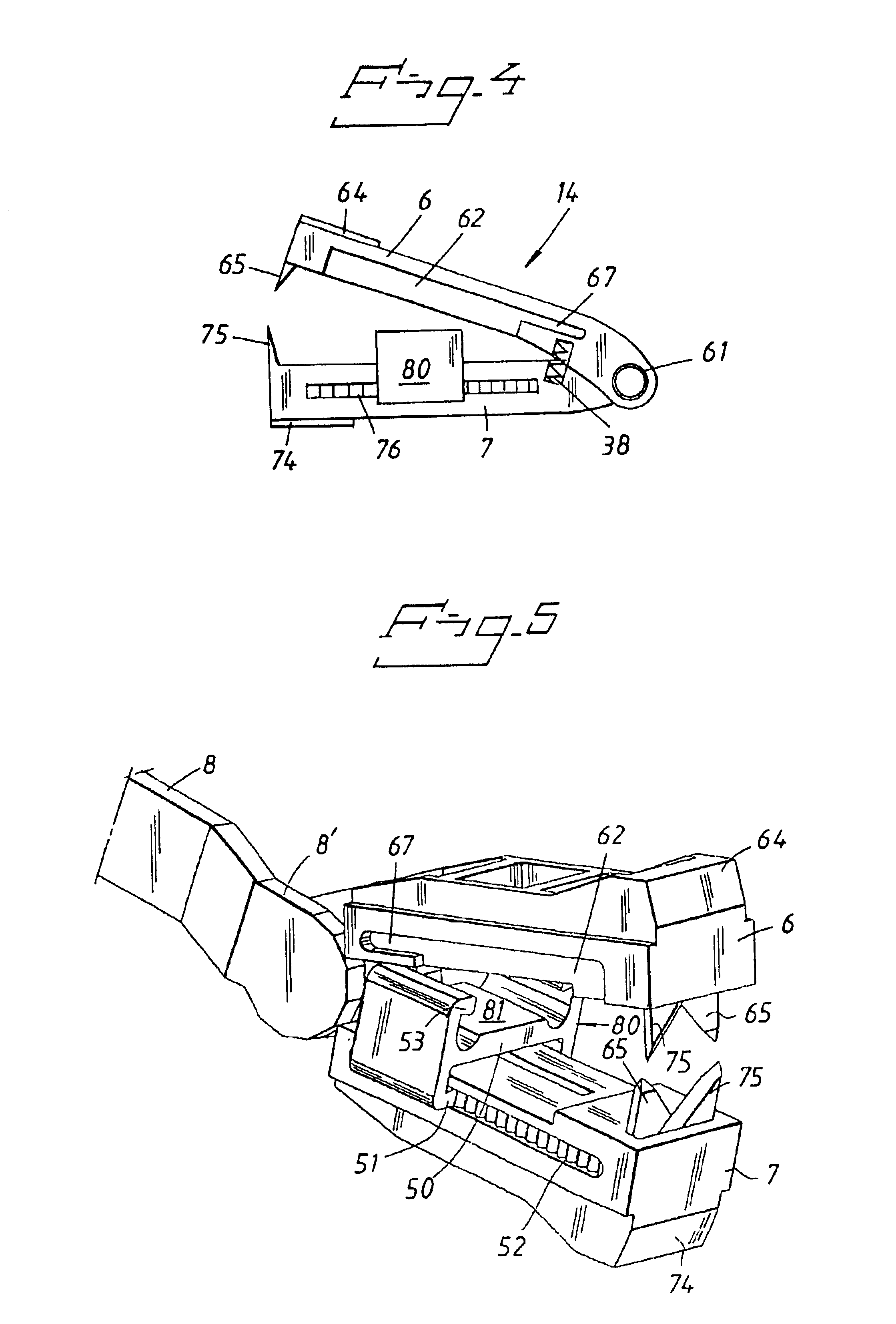
[0018]The tubular pivot mounting 61 between the arms 6, 7 of the cutting unit 14 receives a co-axial pin 60 which is free-bearing from an end-part 8′ of a pull rod 8 that is caused to move axially in the longitudinal direction of the pliers by the mechanism 17 when said mechanism is activated by mutual pivoting of the pliers' legs 4, 5.

[0019]Provided at the freel...


PUM

PropertyMeasurementUnit
Lengthaaaaaaaaaa
Displacementaaaaaaaaaa

Abstract

Cable-stripping pliers having between its clamping jaws a cutting unit with mutually co-acting arms including cutting elements. The cutting unit has an abutment body which is movable in the longitudinal direction of the pliers and which limits the stripping length. The body Includes a latching device for latching the arms together in their closed state. The latching device includes a latching finger that engages a recess in the other arm when the abutment body is displaced to one end and the arms are brought together. The Cable-stripping pliers is arranged so that the cutting unit is removed easily when the clamping jaws are open and the cutting unit is in its closed state.

Description

FIELD OF THE INVENTION[0001]The present invention relates to cable-stripping pliers and a cutting unit that can be used with the pliers.BACKGROUND OF THE INVENTION[0002]The invention thus relates to cable-stripping pliers of the kind disclosed in U.S. Pat. No. 3,915,037 and U.S. Pat. No. 4,112,791 for example.[0003]Such cable-stripping pliers include two clamping jaws that are mounted for pivotal movement in relation to each other and which include two co-acting clamping elements for gripping a cable to be stripped, two legs which are pivotal in relation to each other for pivotally driving the clamping jaws, a cutting unit including two pivotally mounted arms which are spring-biased in a direction away from each other and which have mutually co-acting cutting means at their free ends for cutting through a cable casing to be stripped from the cable, wherein the cutting unit is received between the clamping jaws and adapted for movement therealong, wherein guide means are provided for...

Claims


Application Information

Patent Timeline
IPC IPC(8): H02G1/12B26B27/00
CPCH02G1/1212
Inventor TAPPER, JOHAN
Owner PRESSMASTER
Why Eureka
Try Eureka