
Heated massager with massaging liquid dispenser

a liquid dispenser and heated massage technology, applied in massage, physical therapy, chiropractic devices, etc., can solve the problems of few therapeutic benefits, risk of localized burning on the recipient's skin, and rapid dissipation of heat over the skin surface, so as to facilitate the removal and refilling of the reservoir

Inactive Publication Date: 2005-06-28
WAHL CLIPPER
View PDF14 Cites 74 Cited by
  • Summary
  • Abstract
  • Description
  • Claims
  • Application Information

AI Technical Summary

Benefits of technology

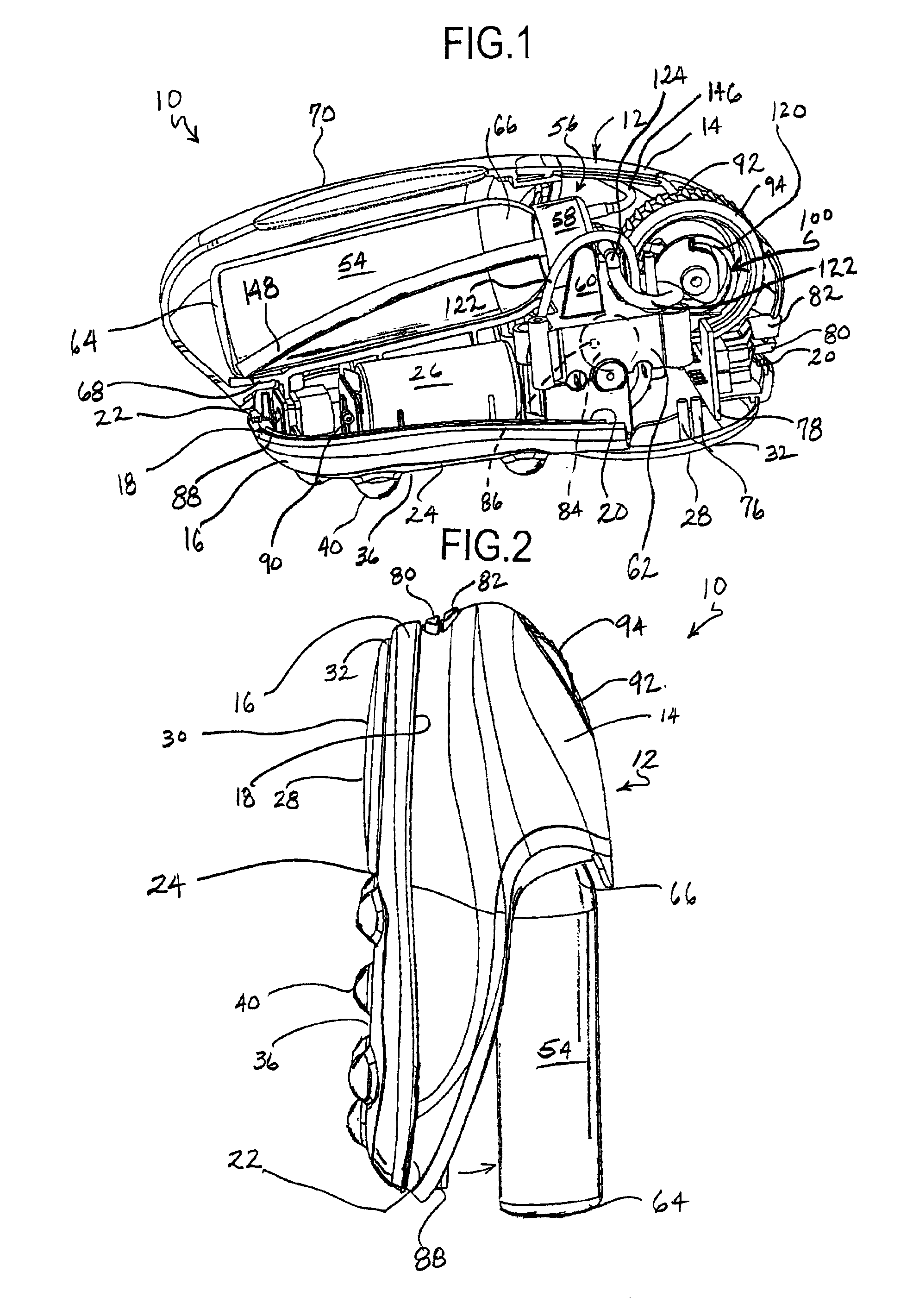
[0014]Also featured on the present massager is a threaded removable bottle reservoir internal to the outer massager shell. The reservoir is accessible by removing a reservoir cover to replace or refill the bottle. To facilitate the removal and refilling of the reservoir, it is received in a pivoting mount which allows the reservoir to assume a generally vertical position upon the placement of the massager in a generally vertical position.

Problems solved by technology

It has been found that when massaging liquid is preheated, the heat is rapidly dissipated over the skin surface, and thus provides few therapeutic benefits.
If the temperature of the massaging liquid is increased, there is a risk of localized burning on the recipient's skin.
However, until now, there have been no massagers which provide heat, massage and a fluid dispensing system in one compact hand-held unit.
A drawback of conventional heated and / or vibrating massagers is that when powered by a line cord, the cord is awkward and gets in the way of the massaging action.
When such units are battery powered, they have a limited running time due to the power draw of the heater and / or the vibrator motor.
Another drawback of conventional hand-held massagers is that when a massaging liquid dispenser is used, there is a tendency to spill the liquid on the unit, which makes it difficult to securely hold.
If the liquid seeps into the unit, internal damage may result.
Still another problem with conventional liquid dispensing massaging units is that there is no way to accurately dispense the massaging liquid upon the skin.
Very often too much liquid is dispensed, which enhances the messiness of the unit described above.

Method used


Image

  • Heated massager with massaging liquid dispenser
  • Heated massager with massaging liquid dispenser
  • Heated massager with massaging liquid dispenser

Examples


Embodiment Construction

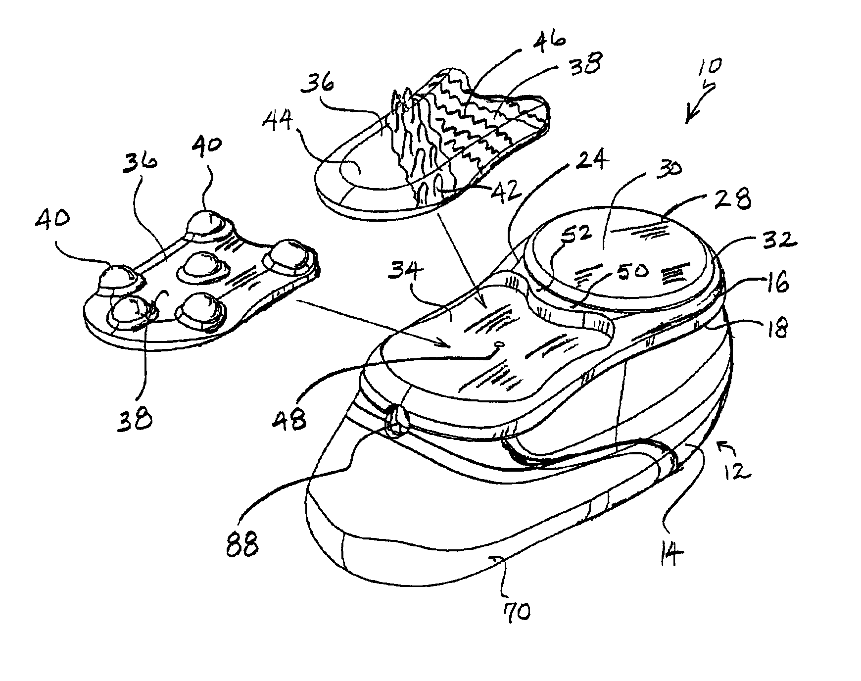
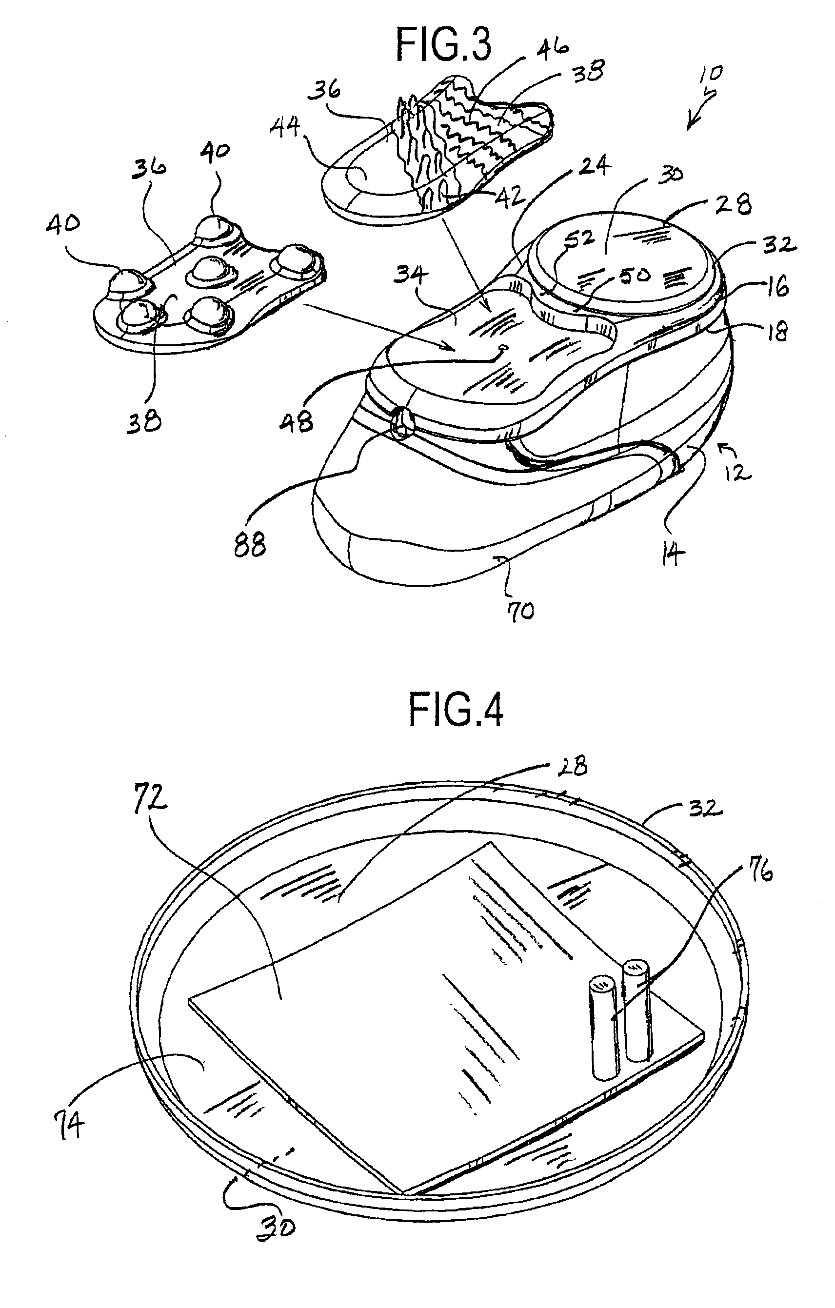
[0025]Referring now to FIGS. 1 and 2, the present massager unit or device is generally designated 10, and includes a housing, generally designated 12. The housing 12, which is preferably made of injection molded plastic, is conceivably made from any durable, rigid material, including metal, wood and / or suitable engineered materials. An upper portion of the housing 12 is referred to as a gripping portion 14, and is preferably configured with an ergonomically “friendly” shape which is easily gripped and comfortably held for extended periods of time. If desired, gripping may be enhanced with textured surfaces and / or resilient pads (not shown) which are fastened or insert molded into the housing 12.

[0026]A lower portion of the housing 12 is referred to as a body-contacting portion 16, which, at its upper end 18 is provided with a resilient gasket 20 which sealingly engages a corresponding lower edge 22 of the gripping portion 14 to prevent the unwanted entry of massaging liquid. The sea...


PUM


Abstract

A hand-held massager includes a housing having a gripping portion and a body-contacting portion, the housing being configured for emitting a massaging liquid and the body-contacting portion being configured for emitting heat to a target surface. The massager also emits a vibration and the amount of vibration is variable, as is the amount of heat and the amount of emitted massaging liquid. A pump is disposed within the housing for dispensing the massaging liquid, and a removable reservoir is in fluid communication with the pump. The reservoir is pivotably mounted to the massager between an operational position in which the reservoir is inclined relative to the body-contacting portion, and a refill position in which the body-contacting portion is placed in a generally vertical position and the reservoir is in a generally parallel position relative to the body-contacting portion.

Description

BACKGROUND OF THE INVENTION[0001]The present invention relates generally to hand-held powered massagers, and specifically to such a massager which dispenses heat and a massaging liquid, in addition to preferably providing vibration as well.[0002]A multitude of massaging devices can be found on the market. Conventional massagers typically provide heat and / or vibration as a massaging force. Such units are also known to be provided with controls to vary the amount of heat and / or massaging action to suit user requirements.[0003]Aromatic and therapeutic massaging liquids, which include oils, lotions and creams, typically are applied by hand. This practice is messy, but provides a therapeutic benefit from the warmth and / or heat from the hand, which enhances the massaging and therapeutic benefits of the massaging liquid.[0004]It has been found that when massaging liquid is preheated, the heat is rapidly dissipated over the skin surface, and thus provides few therapeutic benefits. If the te...

Claims


Application Information

Patent Timeline
IPC IPC(8): A61H15/00A61H23/02A61H15/02
CPCA61H15/0085A61H15/02A61H23/02A61H2201/105A61H2201/0228A61H2201/0242A61H2201/0207
Inventor DIRKS, KEITHMCCAMBRIDGE, JAMES
Owner WAHL CLIPPER
Learn More