[0026]While the invention is susceptible to various modifications and alternative forms, a specific embodiment thereof has been shown by way of example in the drawings and will herein be described in detail. It should be understood, however, that there is no intent to limit the invention to the particular form disclosed, but on the contrary, the intention is to cover all modifications, equivalents, and alternatives falling within the spirit and scope of the invention as defined by the appended claims.
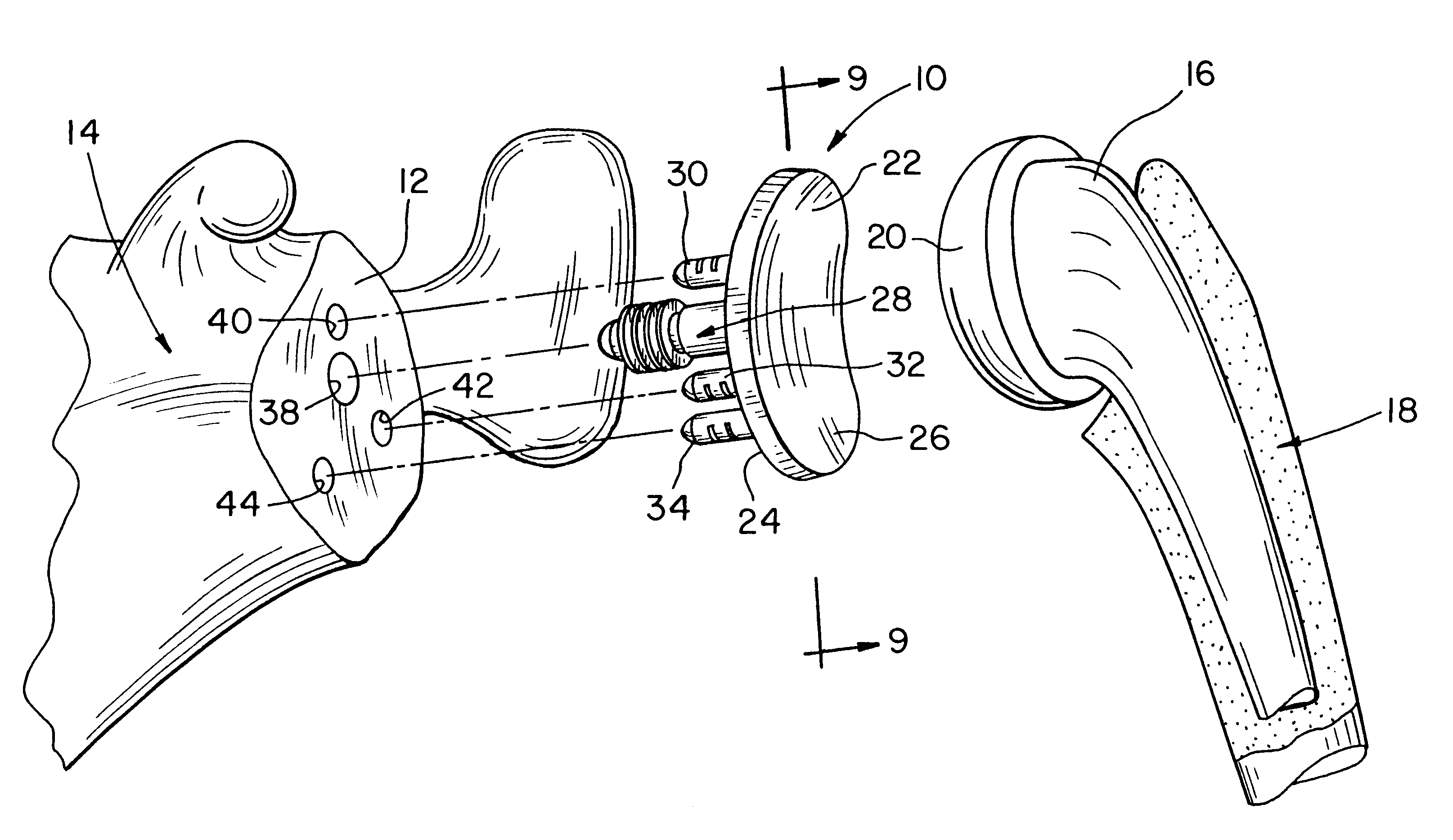
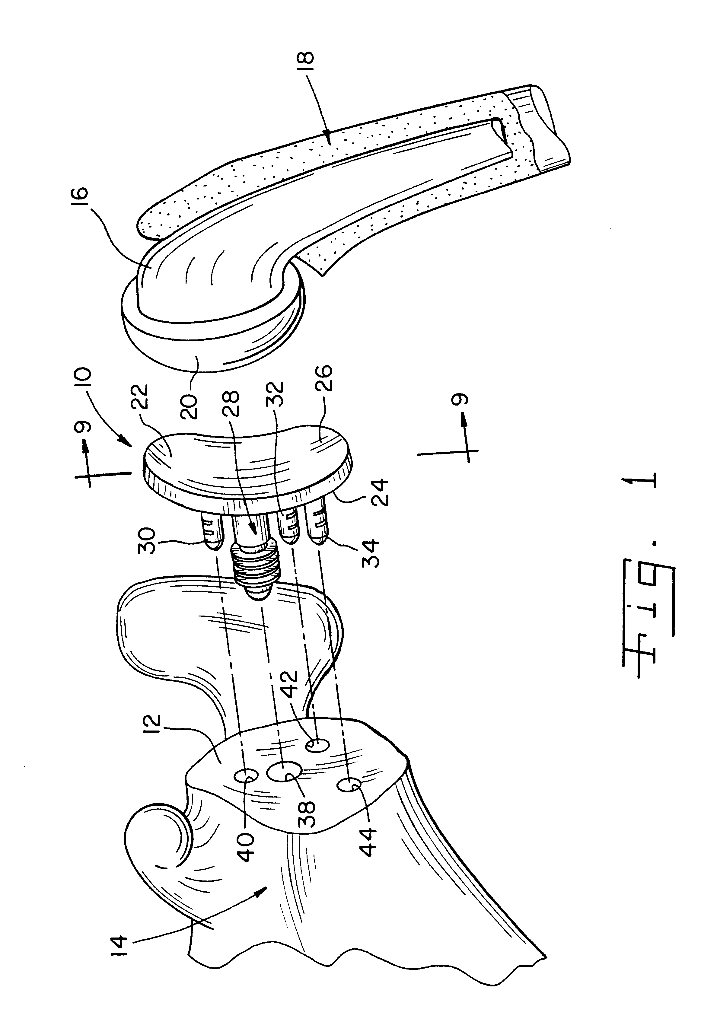
[0027]Referring now to FIG. 1, there is shown a glenoid component 10 located between a glenoid surface 12 of a scapula 14 and a humeral component 16. The humeral component 16 has been implanted or otherwise secured to a humerus 18. As shall be discussed below in greater detail, the glenoid component 10 is configured to be secured to the glenoid surface 12 of the scapula 14 without the use of bone cement in order to replace the natural glenoid surface 12 during a total shoulder replacement procedure. In such a manner, the glenoid component 10 functions as a bearing surface for receiving a head portion of the humerus 18 (i.e. a head portion 20 of the humeral component 16 implanted in the humerus 18).
[0028]As shown in FIGS. 1-8, the glenoid component 10 includes a body portion 22 having a first generally convex surface 24 and a second generally concave surface 26. The convex surface 24 is configured to abut or otherwise contact the glenoid surface 12 of the scapula 14 when the glenoid component 10 is secured thereto. The concave surface 26 of the body portion 22 provides a bearing surface for the head portion 20 of the humeral component 16 implanted into the humerus 18.
[0029]The glenoid component also includes an anchor peg 28 and a number of stabilizing pegs 30, 32, 34. The anchor peg 28 and the stabilizing pegs 30, 32, 34 are secured to the convex surface 24 of the body portion 22 and extend outwardly therefrom. As shown in FIG. 1, the anchor peg 28 is received into an anchor hole 38 which is drilled or otherwise formed in the glenoid surface 12 of the scapula 14, whereas the stabilizing pegs 30, 32, 34 are received into a number of respective stabilizing holes 40, 42, 44 which are also drilled or otherwise formed in the glenoid surface 12 of the scapula 14.
[0030]Although it is contemplated that the anchor peg 28 and/or any one or all of the stabilizing pegs 30, 32, 34 may be embodied as separate components which are secured to the body portion 22, the anchor peg 28 and the stabilizing pegs 30, 32, 34 are preferably integrally formed with one another and the body portion 22. In one exemplary embodiment, the body portion 22, the anchor peg 28, and the stabilizing pegs 30, 32, 34 are integrally molded using a polymeric material such as polyethylene or ultra-high molecular weight polypropylene (UHMWPE).
[0031]As shown best in FIGS. 5 and 6, the anchor peg 28 includes a beveled shaft portion 46 which is secured at its proximal end to the convex surface 24. The distal end portion of the shaft portion 46 has a conical tip 48 defined therein which is provided as a “lead in” to facilitate insertion of the anchor peg 28 into the anchor hole 38 drilled in the glenoid surface 12 of the scapula 14.
[0032]In addition to the conical tip 48, the distal end portion of the shaft portion 46 also has a number of fins 50 secured thereto. The fins 50 extend radially outwardly from the shaft portion 46 of the anchor peg 28 in a substantially perpendicular direction relative to the shaft portion 46 such that the outer diameter of each of the fins 50 is greater than the outer diameter of the shaft portion 46. Each of the fins 50 preferably extends continuously around the entire outer periphery of the shaft portion 46, although the fins 50 may alternatively be embodied as a series of individual flange sections which line substantially all of the outer periphery of the shaft portion 46.
[0033]Although the anchor peg 28 is herein shown in the figures to include four fins 50, it should be appreciated that the anchor peg 28 may be embodied to include any number of fins. For example, the anchor peg 28 may be embodied to include only a single (i.e. one) fin 50. In addition, although each of the fins 50 is herein shown in the figures to possess the same sized outer diameter, it should be appreciated that other fin configurations are also contemplated for use with the glenoid component 10 of the present invention. For example, the fins 50 may be provided in a tapered configuration in which the respective outer diameters of the fins 50 gradually increases from the distal end of the shaft portion 46 to the proximal end portion of the shaft portion (i.e. the fin positioned on the distal end of the shaft portion 46 has a smaller diameter relative to the fin positioned on the proximal end of the shaft portion 46). In such a configuration, the anchor hole 38 drilled in the scapula 14 would be drilled in a similarly tapered manner so as to provide a corresponding sidewall configuration for engagement by the fins 50.
[0034]Although it is contemplated that the fins 50 may be embodied as separate components which are secured to the shaft portion 46 of the anchor peg 28, the fins 50 are preferably integrally formed with the shaft portion 46 of the anchor peg 28. Consistent with as described above, in one exemplary embodiment, the fins 50 are integrally molded with the shaft portion 46 of the anchor peg 28 (and hence also integrally molded with the body portion 22 and the stabilizing pegs 30, 32, 34 of the glenoid component 10) using a polymeric material such as polyethylene or ultra-high molecular weight polypropylene (UHMWPE).
[0035]As shown in FIG. 9, the fins 50 are configured to curl, bend, or otherwise deform when the anchor peg 28 is inserted into the anchor hole 38. This is caused when the fins 50 are advanced into the anchor hole 38 since it is drilled so as to have a diameter which is slightly larger than the diameter of the shaft portion 46 of the anchor peg 28, yet smaller than the outer diameter of the fins 50 thereby causing deformation of the fins 50 upon contact with the sidewalls of the anchor hole 38 as the fins 50 are “forced” into the anchor hole 38. Such deformation of the fins 50 allows the fins 50 to function as upwardly turned “barbs” which secure the glenoid component 10 to the scapula 14 by providing resistance to removal or “pull out” of the anchor peg 28 from the anchor hole 38 much in the same way that the threads of a screw provide resistance to pull out of the screw from the material into which it is driven. In addition, over a period of time subsequent to securement of the glenoid component 10 to the scapula 14, bone tissue or other types of tissue will grow into the spaces between the fins 50 thereby providing further resistance to pull out of the anchor peg 28 from the anchor hole 38.
[0036]Moreover, the fins 50 of the present invention are configured in a manner which provides numerous advantages over heretofore designed anchoring structures. For example, the fins 50 are configured to be relatively thin in design and possess a relatively large outer diameter thereby providing for a relatively large amount of deformation or “curling” which in turn creates a large amount of anchoring force when the anchor peg 28 is inserted into the anchor hole 38. In one exemplary embodiment, each of the fins 50 has a nominal thickness of 0.023 inch with a distance of 0.052 inch between adjacent fins. Moreover, in such an exemplary embodiment, the fins 50 have an outer diameter of 0.346 inch and extend outwardly from a shaft portion 46 which has a diameter of 0.188 inch.
[0037]Such a configuration of the fins 50 as described above eliminates the need for the use of bone cement to secure the anchor peg 28 to the glenoid surface 12 of the scapula 14 thereby reducing the complexity of a typical total shoulder replacement procedure along with eliminating any potential shortcomings associated with the use of bone cement. In particular, the above-described configuration of the fins 50 provides a glenoid component 10 which “locks” into place upon insertion into the anchor hole 38 drilled in the scapula 14. More specifically, preliminary laboratory tests have indicated that when inserted into a test material such as white pine wood, the removal force required to remove the glenoid component 10 is over twice as large in magnitude as the insertion force required to press fit the glenoid component 10 into the test material. The creation of such a relatively large removal force facilitates the use of the glenoid component 10 without the use of bone cement.
[0038]The stabilizing pegs 30, 32, 34 are provided to prevent rotation or other types of movement of the body portion 22 of the glenoid component 10 relative to the scapula 14 once the glenoid component 10 has been secured to the glenoid surface 12. Each of the stabilizing pegs 30, 32, 34 includes a cylindrical shaft portion 56 which is secured at its proximal end to the convex surface 24 of the body portion 22. The distal end of each of the shaft portions 56 has a conical tip 58 defined therein which, similarly to as described above in regard to the anchor peg 28, functions as a “lead in” to facilitate insertion of the stabilizing pegs 30, 32, 34 into their respective stabilizing holes 40, 42, 44 drilled in the glenoid surface 12 of the scapula 14.
[0039]The stabilizing pegs 30, 32, 34 may be arranged in any orientation on the convex side 24 of the body portion 22 which fits the needs of a given glenoid component 10. For example, as shown best in FIG. 7, the stabilizing peg 30 may be spaced apart from the anchor peg 28 in a direction which is substantially opposite from the direction in which the stabilizing pegs 32, 34 are spaced apart from the anchor peg 28. Moreover, one arrangement of the stabilizing pegs 30, 32, 34 which has been found to be particularly useful for preventing rotation or other types of movement of the glenoid component 10 relative to the scapula 14 is an arrangement shown in FIG. 7 in which a first pair of pegs (i.e. the anchor peg 28 and the stabilizing peg 30) are positioned in a normal relationship with a second pair of pegs (i.e. the stabilizing pegs 32, 34). In particular, as shown in FIG. 7, the anchor peg 28 and the stabilizing peg 30 are aligned with respect to one another along a first imaginary line 60, whereas the stabilizing peg 32 and the stabilizing peg 34 are aligned with respect to one another along a second imaginary line 62. The imaginary line 60 is normal or otherwise substantially perpendicular to the imaginary line 62.
[0040]In addition, it should be appreciated that any number of stabilizing pegs may be utilized to fit the needs of a given glenoid component 10. In particular, although the glenoid component 10 is described herein as having three stabilizing pegs, and has significant advantages thereby in the present invention, it should be appreciated that the glenoid component 10 may be alternatively embodied to include any number of stabilizing pegs. For example, the glenoid component 10 may be embodied to include only a single (i.e. one) stabilizing peg.
[0041]Moreover, as shown in FIGS. 3-5 and 8, the stabilizing pegs 30, 32, 34 may alternatively be configured to have a number of serrations 64 defined therein. The serrations 64 may be utilized in a similar manner as the fins 50 of the anchor peg 28 in that over a period of time subsequent to securement of the glenoid component 10 to the scapula 14, bone tissue or other types of tissue will grow into the serrations 64 thereby providing resistance to pull out of the glenoid component 10 from its secured position on the glenoid surface 12 of the scapula 14. Moreover, if a particular surgeon or procedure requires (or simply desires) the use bone cement in the stabilizing holes 40, 42, 44 due to, for example, governmental regulation or the like, the serrations 64 may be utilized to receive a portion of the bone cement in order to increase the area of contact between the bone cement and the stabilizing pegs 30, 32, 34 thereby increasing the bond between the stabilizing pegs 30, 32, 34 and the walls of the stabilizing holes 40, 42, 44.
[0042]Hence, the glenoid component 10 may be secured to the glenoid surface 12 of the scapula 14 in a number of different manners. In a first or “cementless” manner, each of the anchor peg 28 and the stabilizing pegs 30, 32, 34 is press fit or otherwise interference fit into their respective holes 38, 40, 42, 44 without the use of bone cement. In a second or “cemented” manner, the anchor peg 28 is press fit or otherwise interference fit into the anchor hole 38 in the same manner as described above; however, the stabilizing pegs 30, 32, 34 are clearance fit into their respective stabilizing holes 40, 42, 44 with the use of bone cement. Such multiple uses of the glenoid component 10 of the present invention provides flexibility in regard to its use thereby fulfilling the needs of a given surgeon or shoulder replacement procedure.
OPERATION OF THE PRESENT INVENTION
[0043]In operation, the glenoid component 10 of the present invention is utilized in the performance of a total shoulder replacement procedure in order to provide an artificial bearing surface for the head portion of the humerus without the use of bone cement. In particular, the anchor hole 38 and the stabilizing holes 40, 42, 44 are first drilled or otherwise formed in the glenoid surface 12 of the scapula 14 by use of a suitable drilling tool (not shown). It should be appreciated that a drill guide or pattern (not shown) may be utilized to properly position and align the holes 38, 40, 42, 44 on the glenoid surface 12 of the scapula 14.
[0044]Once the holes 38, 40, 42, 44 have been drilled in the glenoid surface 12 of the scapula 14, the glenoid component 10 is secured to the scapula 14. In particular, the glenoid component 10 is oriented such that the anchor peg 28 and the stabilizing pegs 30, 32, 34 are pointed in the general direction of the glenoid surface 12 of the scapula 14. Thereafter, the glenoid component 10 is advanced toward the glenoid surface 12 such that the anchor peg 28 and each of the stabilizing pegs 30, 32, 34, are contemporaneously advanced into the anchor hole 38 and the stabilizing holes 40, 42, 44, respectively.
[0045]As described above, the fins 50 are configured to curl, bend, or otherwise deform when the anchor peg 28 is inserted into the anchor hole 38 so as to allow the fins 50 to function as “barbs” which secure the glenoid component 10 to the scapula 14 by providing resistance to pull out of the anchor peg 28 from the anchor hole 38 much in the same way that the threads of a screw provide resistance to pull out of the screw from the material into which it is driven. In addition, as described above, over time a period of time subsequent to securement of the glenoid component 10 to the scapula 14, bone tissue or other types of tissue will grow into the spaces between the fins 50 thereby providing further resistance to pull out of the anchor peg 28 from the anchor hole 38.
[0046]Hence, insertion of the anchor peg 28 into the anchor hole 38 anchors or otherwise retains the body portion 22 of the glenoid component 10 into contact with the glenoid surface 12 of the scapula 14. Moreover, insertion of the stabilizing pegs 30, 32, 34 into the stabilizing holes 40, 42, 44 in the manner described above prevents rotation or other types of movement of the body portion 22 of the glenoid component 10 relative to the glenoid surface 12 of the scapula 14.
[0047]Once the glenoid component 10 has been secured to the glenoid surface 12 of the scapula 14 in the manner described, the concave surface 26 of the body portion 22 of the glenoid component 10 provides a bearing surface for receiving the head portion 20 of the humeral component 16 implanted in the humerus 18. In such a manner, the concave surface 26 of the body portion 22 functions as a suitable artificial replacement for the natural glenoid surface 12 of the scapula 14.
[0048]Hence, as described herein, the glenoid component 10 of the present invention provides numerous advantages over heretofore designed glenoid components. For example, the glenoid component 10 is configured to be secured to the glenoid surface 12 of the scapula 14 without the use of bone cement. Moreover, the glenoid component 10 of the present invention is preferably provided as a one-piece, integrally molded component thereby overcoming many of the drawbacks associated with heretofore designed multiple-piece designs.
[0049]While the invention has been illustrated and described in detail in the drawings and foregoing description, such an illustration and description is to be considered as exemplary and not restrictive in character, it being understood that only the preferred embodiment has been shown and described and that all changes and modifications that come within the spirit of the invention are desired to be protected.
[0050]There are a plurality of advantages of the present invention arising from the various features of the glenoid component described herein. It will be noted that alternative embodiments of the glenoid component of the present invention may not include all of the features described yet still benefit from at least some of the advantages of such features. Those of ordinary skill in the art may readily devise their own implementations of a glenoid component that incorporate one or more of the features of the present invention and fall within the spirit and scope of the present invention as defined by the appended claims.
[0051]For example, the embodiment of one bearing component in accordance with the concepts of the present invention has herein been described in regard to the glenoid component 10. However, it should be appreciated that the concepts of the present invention may also be incorporated into an acetabular, patellar, femoral, humoral, tibial, ulnar, radial, wrist, and/or ankle component for a prosthetic joint assembly.