Visibly transparent dyes for through-transmission laser welding

a laser welding and transparent technology, applied in the field of transparent dyes, can solve the problems of slow linear welding speed, poor appearance of final welds, uncontrolled radiation scattering, etc., and achieve the effect of reducing the cost of dye production

Inactive Publication Date: 2005-06-28
GENTEX CORP
View PDF76 Cites 99 Cited by
  • Summary
  • Abstract
  • Description
  • Claims
  • Application Information

AI Technical Summary

Benefits of technology

[0016]It is an object of the invention to identify dyes that are also extremely soluble, add little or no light scattering and efficiently absorb laser radiation and via vibronic relaxation transmit heat to weld plastics.
[0022]A second stage quantitative calculation screens dyes for their contribution to the transparency of the substrate. By taking into consideration the results from both stages, the usefulness of a candidate dye can be quickly, easily and inexpensively determined. The key is identifying the most critical parameters that determine a dyes ability to perform in aesthetically demanding welding applications and subsequently discovering ways to rate the dyes and compare them to each other.

Problems solved by technology

Radiation scattering is an uncontrolled and relatively inefficient method of converting the incident radiation to heat.
Accordingly, radiation scattering may require larger amounts of the brazing compound, greater amounts of incident radiation, slower linear welding speeds, and may result in a poor appearance of the final weld.
However, there are no known compounds or welding techniques which can provide predicable results in demanding aesthetic industrial and consumer applications like automobile moldings and food and beverage packaging.
Several severe limitations are inherent in the disclosed methods.
First, these metallic brazing compounds are only suitable for welding glass.
Second, the patent admits that some experiments with Nd-YAG pulsed lasers have resulted in some nonlinear effects at the weld joint which are not entirely understood.
In addition, the use of a polychromatic, non-coherent radiation source requires the presence of cumbersome focusing elements and masks.
An inordinate amount of experimentation, and expense associated with those rarer compounds, may be required to select a general purpose dye for aesthetically demanding applications.

Method used


Image

  • Visibly transparent dyes for through-transmission laser welding
  • Visibly transparent dyes for through-transmission laser welding
  • Visibly transparent dyes for through-transmission laser welding

Examples


example 1

Calculating the Absorbance Ratio for a Candidate Dye

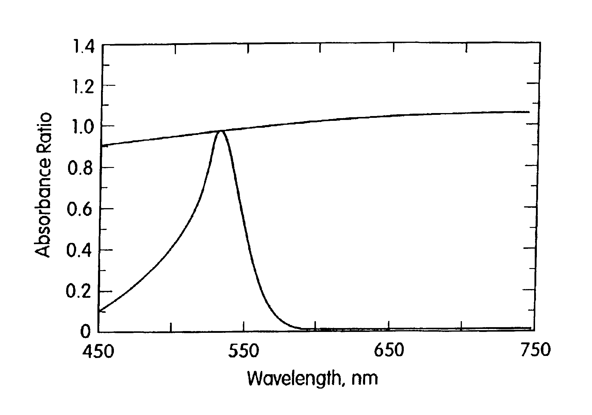
[0042]The substrate was doped with a notch absorber at a concentration of between 0.05 and 0.10 grams per pound of substrate. In this example, the notch includes the 532 nm wavelength of the doubled Nd:YAG laser. Accordingly the laser welding wavelength equals 532 nm (lww=532 nm). This value used in the denominator of Equation 1 will be constant for all calculations with this absorber.

[0043]Next we calculate the reference point for our Absorbance Ratio. The reference point by definition has an optical density (OD) of unity. The reference point is where the wv equals lww (532 wl−532 lww) as is calculated in Equation 1-A as follows: Absorbance⁢ ⁢Ratio⁡(OD)=OD⁢ ⁢(Substrate+Dye@532⁢ ⁢nm)-OD⁢ ⁢(Substrate@532⁢ ⁢nm)OD⁢ ⁢(Substrate+Dye@532⁢ ⁢nm)-OD⁢ ⁢(Substrate@532⁢ ⁢nm)=1Equation⁢ ⁢1⁢-⁢A

Note that the Absorbance Ratio will remain at 1 independent of concentration, substrate type, substrate transmission characteristics or substrate thicknes...

example 2

Calculating the Absorbance Ratio for Carbon Black

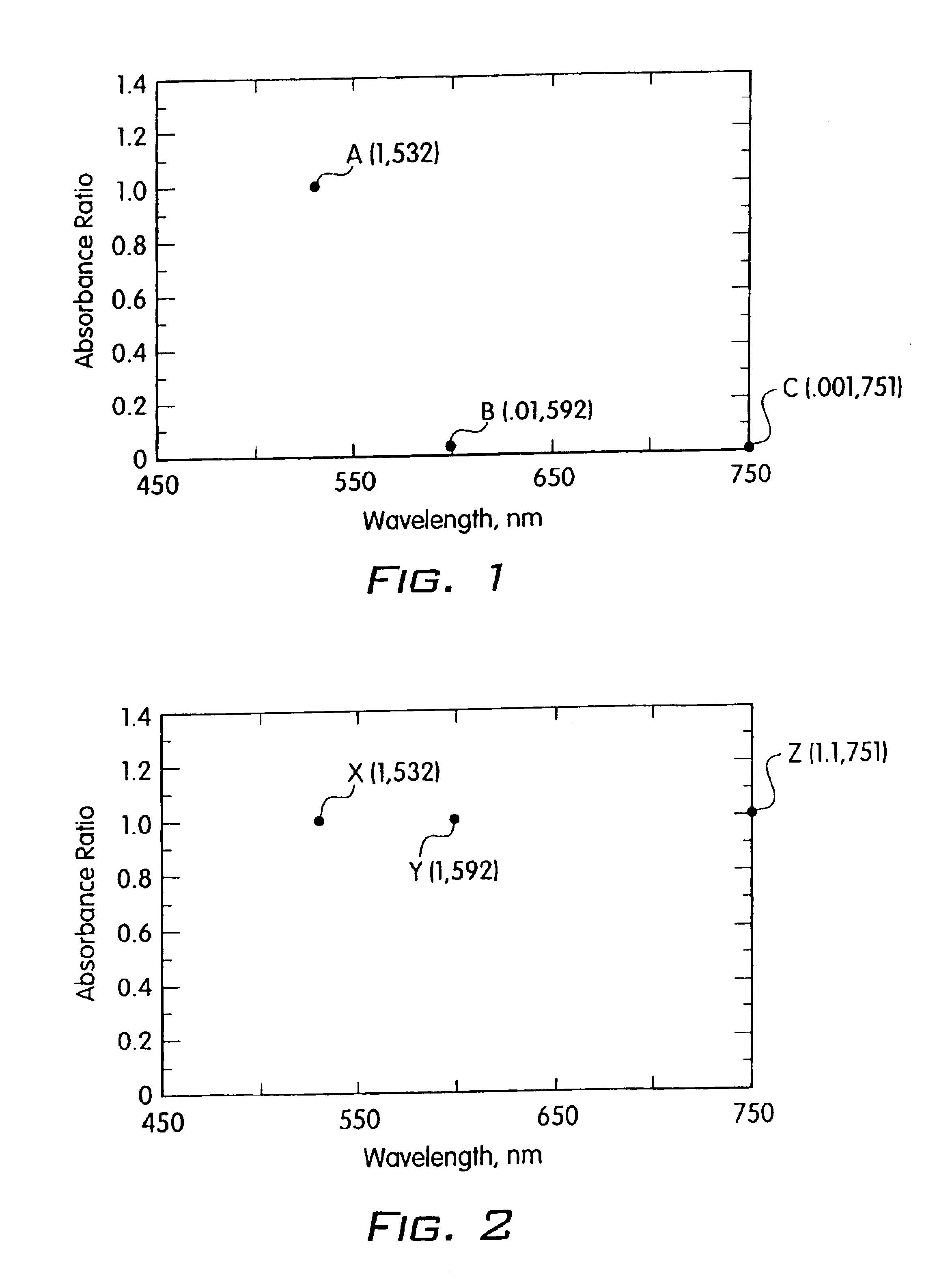
[0046]Next we calculate the Absorbance Ratio for a prior art compound, for example carbon black. We use the same reference point of 532 nm for the lww and we use the same wavelengths as above, 532 nm, 592 nm and 751 nm, for the wv value in the numerator. These points as shown as X, Y and Z on FIG. 2. The Absorbance Ratio at the reference point (X) is 1.0. The Absorbance Ratios at point Y is 1.0 and at point Z is 1.1. The following table presents a side-by-side comparison:

[0047]

Absorbance Ratios (ref. graph point)Wavelength532 nm AbsorberCarbon Black532 nm 1.0 (A)1.0 (X)592 nm 0.01 (B)1.0 (Y)751 nm0.001 (C)1.1 (Z)

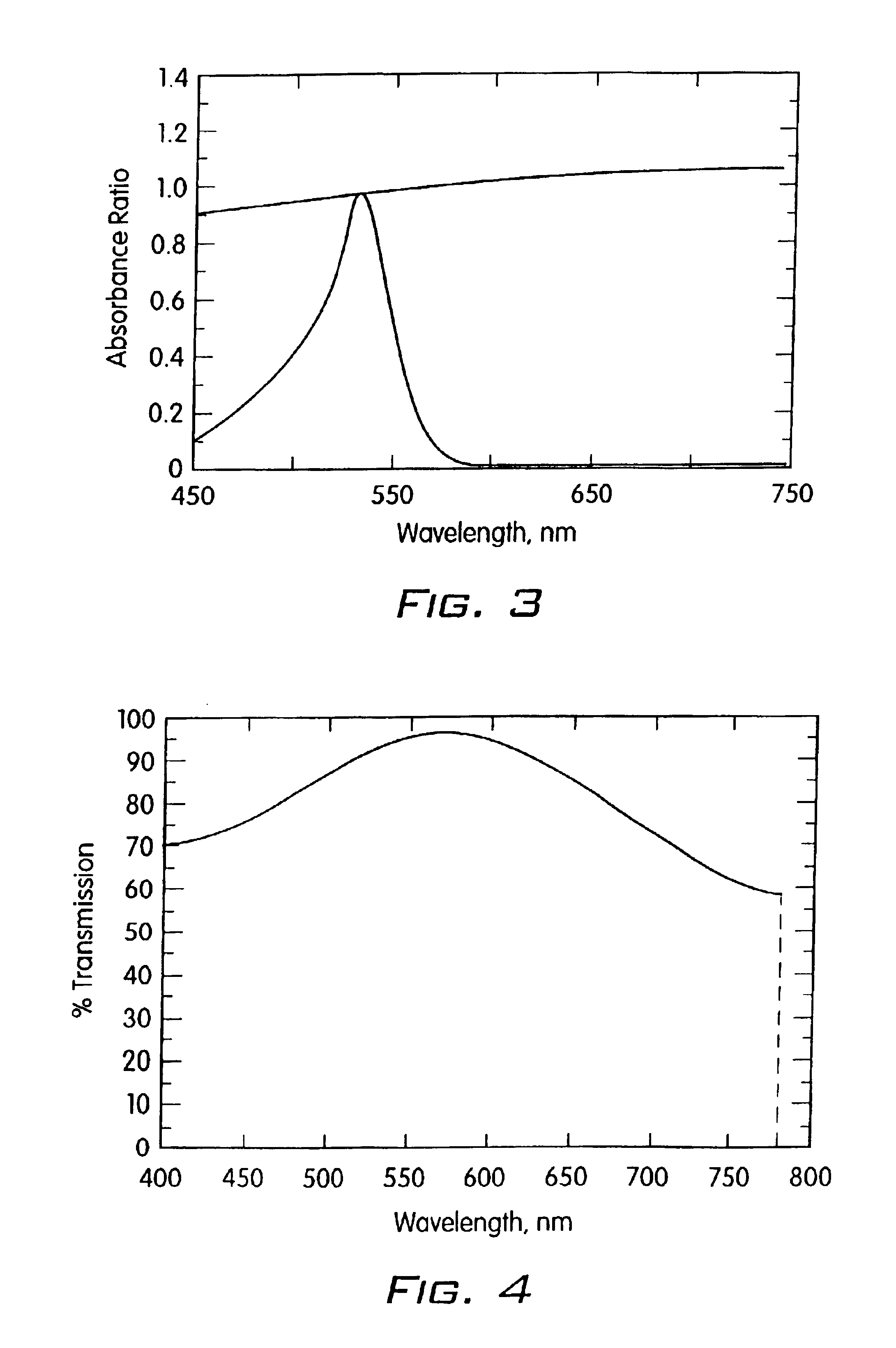
[0048]FIG. 3 shows the full Absorbance Ratio curves for the 532 absorber and carbon black together. This graph readily shows that the 532 absorber effectively absorbs at the desired laser welding wavelength and absorbs 100 times and 1000 times less strongly at other points within the visible spectrum. Carbon black abs...


PUM

PropertyMeasurementUnit
transparentaaaaaaaaaa
wavelengthaaaaaaaaaa
wavelengthsaaaaaaaaaa

Abstract

Selection criteria for dyes that predicts efficiency and performance for plastics welding. A first stage quantitative calculation screens dyes that possess an absorption band that can be matched to a laser that is suitable for plastic welding. It also identifies absorption troughs in the visible spectrum and establishes relationships between the relative optical densities of the absorption band and trough. A second stage quantitative calculation screens dyes for their contribution to the transparency of the substrate. By combining these two stages, the usefulness of a candidate dye can be quickly, easily and inexpensively determined.

Description

CROSS REFERENCE TO RELATED APPLICATIONS[0001]This is a continuation of U.S. patent application Ser. No. 09 / 711,277 filed Nov. 10, 2000, now abandoned.BACKGROUND OF THE INVENTION[0002]1. Field of the Invention[0003]The invention relates to visibly transparent dyes and a method for using same in through-transmission laser welding. More particularly, it relates to the use of dyes in aesthetically demanding applications.[0004]2. The Prior Art[0005]Many different materials are used as brazing compounds or radiation scattering compounds in plastic welding. Generally the top substrate, through which the radiation is first transmitted before reaching the joint region, is designed to transmit a high portion of the welding radiation.[0006]Brazing compounds are added to the joint region to absorb or scatter the incident radiation to melt the facing surfaces that comprise the joint to be welded. Radiation scattering is an uncontrolled and relatively inefficient method of converting the incident...

Claims


Application Information

Patent Timeline
Patent Type & Authority Patents(United States)
IPC IPC(8): B29C65/14B29C65/16
CPCB29C65/1635C08K5/0041B29C65/1606B29C65/1674B29C65/168B29C65/1683B29C65/1696B29K2023/00B29K2033/12B29K2067/00B29K2069/00B29K2077/00B29K2995/0026Y10S428/913B29C65/1616B29C66/73921B29C66/71Y10T428/31504Y10T428/8305
Inventor SALLAVANTI, ROBERT A.FRIEDER, III, LEONARD PETER
Owner GENTEX CORP
Why Eureka
Try Eureka