
Optical disc apparatus and method for reading information from an optical disk having tracks and spaces between the tracks on which address information is recorded

an optical disc and information technology, applied in the field of digital disc recording and reproducing signals, can solve the problems of further lowering the lpp address detection ratio and low reliability during recording, and achieve the effect of improving reliability during recording

Inactive Publication Date: 2005-06-28
PANASONIC CORP +1
View PDF18 Cites 16 Cited by
  • Summary
  • Abstract
  • Description
  • Claims
  • Application Information

AI Technical Summary

Benefits of technology

The present invention provides an optical disc apparatus that can accurately detect whether it is recording data in the correct track and improve reliability during recording. This is achieved by separately installing a differential amplifying circuit for detecting a modulation signal and an LPP address signal, and adjusting the balance of the differential amplifying circuit for address detection based on the recording and reproducing conditions of the apparatus. The guiding grooves of the disc are modulated in the radial direction by the frequency which serves as the reference signal of clocks required for reproduction and recording of the information, and an automatic gain control circuit can be added to expand the LPP address reading margin against disturbance factors such as defocus, off-track, tilt, etc. of the optical head or the disc.

Problems solved by technology

However, when the track jump of the optical head is detected by using the tracking error signal, there may be misdetection.
Since in the conventional optical disc apparatus 80 (FIG. 8) the LPP address detection ratio during recording or reproducing the recorded tracks lowers, there are not many methods to detect whether or not the apparatus was recording the data in the correct track by detecting a primarily tracking error signal, and especially, the reliability during recording was low.
In addition, depending on the off-track condition of the optical head, there was a problem of further lowering the LPP address detection ratio.

Method used


Image

  • Optical disc apparatus and method for reading information from an optical disk having tracks and spaces between the tracks on which address information is recorded
  • Optical disc apparatus and method for reading information from an optical disk having tracks and spaces between the tracks on which address information is recorded
  • Optical disc apparatus and method for reading information from an optical disk having tracks and spaces between the tracks on which address information is recorded

Examples


Embodiment Construction

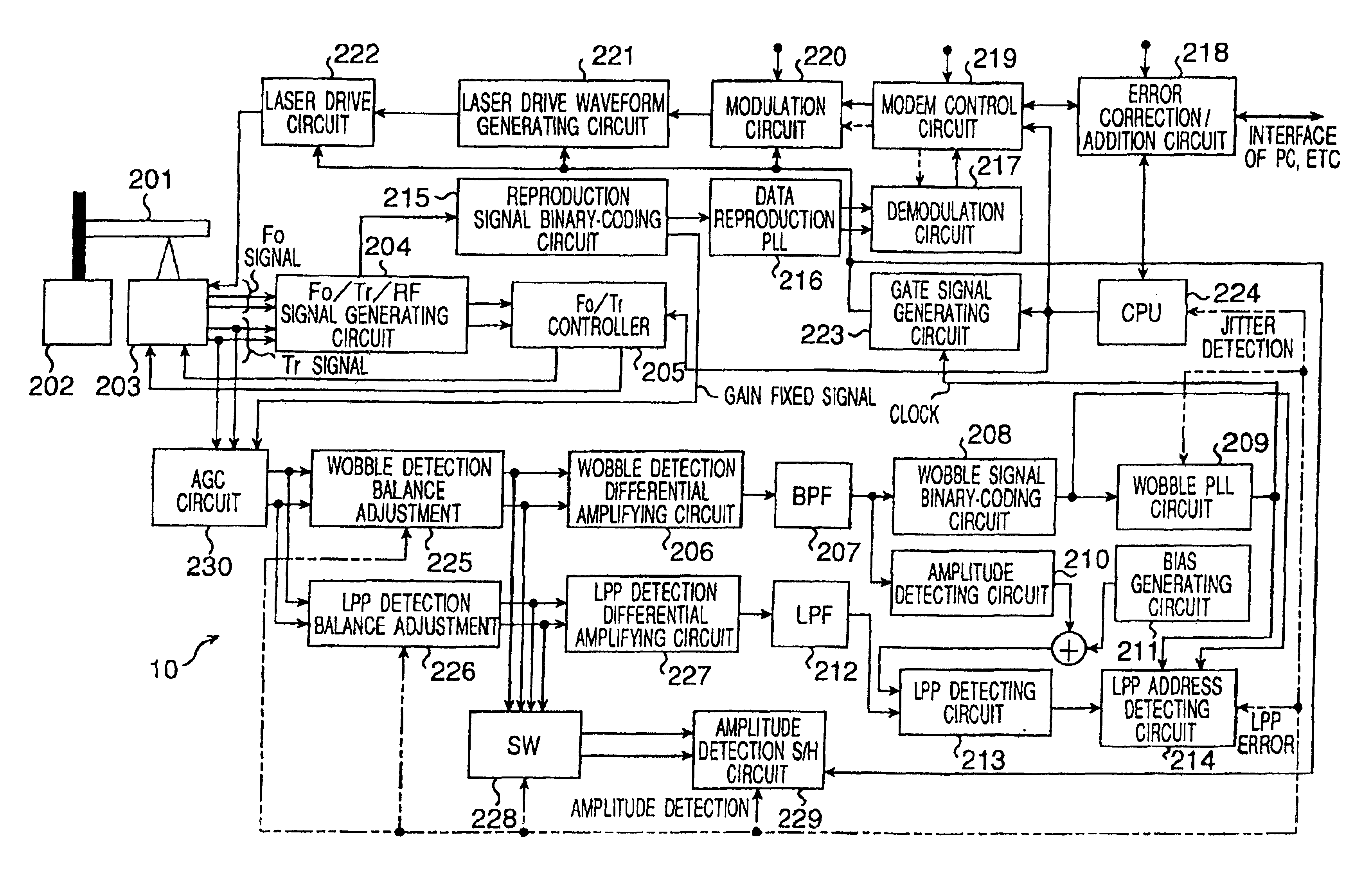
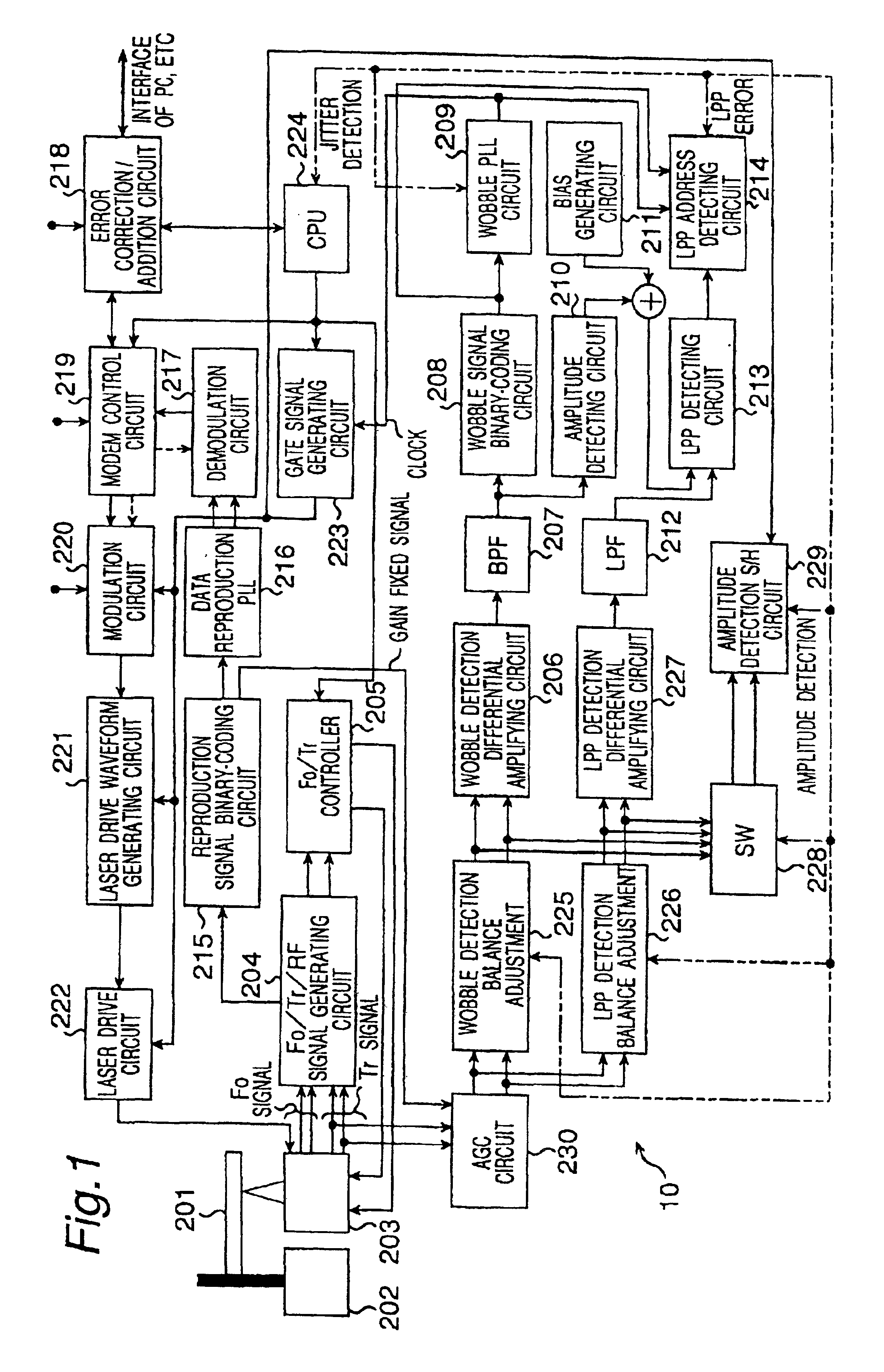
[0038]Referring now to the attached figures, an embodiment of the present invention will be described in detail. FIG. 1 is a block diagram of an optical disc recording and reproducing apparatus 10 in an embodiment of the present invention. Now, each component of the optical disc recording and reproducing apparatus 10 will be described. The optical disc recording and reproducing apparatus 10 records / reproduces the information to / from an optical disc (for example, DVD-R / RW disc) 201. The optical disc recording and reproducing apparatus 10 comprises a disc motor 202, an optical head 203 equipped with focusing detectors, a reproduction signal detector, and tracking detectors for detecting the light, a servo signal / reproduction signal generating circuit 204 for generating a focus error signal, tracking error signal, and reproduction signal from the light amount signals from the detectors, a focus / tracking control section 205 that allows the optical head 203 to keep tracking the guiding g...


PUM

PropertyMeasurementUnit
compatibilityaaaaaaaaaa
timeaaaaaaaaaa
frequencyaaaaaaaaaa

Abstract

An optical disc apparatus reads the address information from an optical disc which has tracks and track spaces formed between tracks. The apparatus has an optical head which irradiates the disc with light and includes tracking detectors, divided into a first detector and a second detector in a track direction, detecting the light reflected from the disc and outputting detection signals, an adjusting circuit which adjusts amplitudes of the first and second detection signals and outputs the signals at a position where the address information is recorded, a differential amplifying circuit which outputs the differential signal which is the difference between the adjusted first and second detection signals, and an address detecting circuit which detects the address information based on the differential signal. As a result, the optical disc apparatus accurately detects whether information is being recorded on a correct track and improves the reliability during recording.

Description

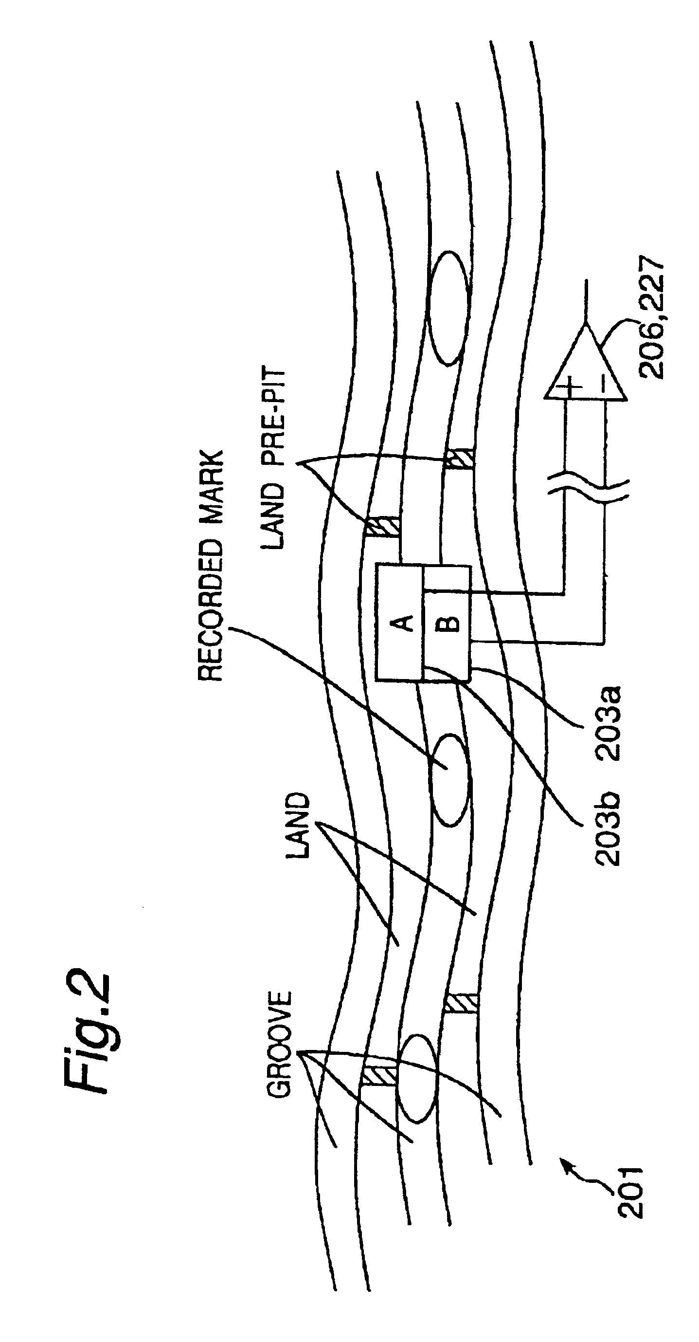
BACKGROUND OF THE INVENTION[0001]The present invention relates to a technique for recording and reproducing signals recorded in a digital disc.[0002]There are DVD-R / RW as formats of optical discs for recording and reproducing information. The primary feature of these formats lies in the address information required for identifying the address in recording and reproducing information which is formed on land portions of the disc in order to improve compatibility with the DVD-ROM format. A track is a region of the optical disc in which the information to be reproduced is recorded as marks. The address information is formed at the space section (also called the land) between guiding grooves (also called grooves) of the disc, to which information to be reproduced is recorded. This address is also called “land pre-pit address” or “LPP address.” At the time of tracking the recorded track(s), tracking detectors of the apparatus-detect the incident light and generate a plurality of signals r...

Claims


Application Information

Patent Timeline
Patent Type & Authority Patents(United States)
IPC IPC(8): G11B27/19G11B27/24G11B7/005G11B7/007G11B7/00G11B7/13G11B20/10
CPCG11B7/005G11B7/007G11B7/131G11B27/24G11B7/00745G11B2220/2562G11B2220/216G11B2220/218G11B20/10009
Inventor INOKUCHI, CHIKASHIKOISHI, KENJIKONNO, KOHJYUOSADA, YUTAKAOOHTA, MITSUHIKOKAWAI, TAKASHI
Owner PANASONIC CORP
Learn More