Method and apparatus for generating a large number of codes having desirable correlation properties

a technology of correlation properties and codes, applied in the direction of multi-component code generation, electrical apparatus, multiplex communication, etc., can solve the problems of less suitable spectral properties, correlation properties, and the tendency to produce a limited number of codes having desirable correlation properties

Inactive Publication Date: 2005-06-28
TIME DOMAIN
View PDF3 Cites 132 Cited by
  • Summary
  • Abstract
  • Description
  • Claims
  • Application Information

AI Technical Summary

Benefits of technology

[0034]The present invention provides a method and apparatus for generating codes that may also be referred to as number sequences, which have desirable correlation properties for use by UWB, CDMA, TDMA, FDMA, or OFDM systems. The generated codes can be used to specify temporal and non-temporal signal characteristics including pulse position in time, amplitude, width, type, phase, phase difference, frequency, spreading code, etc. The invention includes methods for generating the codes, apparatuses employing the codes, and methods for employing the codes. The invention involves defining a signal characteristic value layout and mapp

Problems solved by technology

Unlike conventional spread-spectrum systems, impulse radio systems typically do not employ time-hopping codes for the purpose of energy spreading.
Such ‘random-like’ codes are attractive for certain applications since they tend to spread spectral energy over multiple frequencies while having ‘good enoug

Method used


Image

  • Method and apparatus for generating a large number of codes having desirable correlation properties
  • Method and apparatus for generating a large number of codes having desirable correlation properties
  • Method and apparatus for generating a large number of codes having desirable correlation properties

Examples


example 1

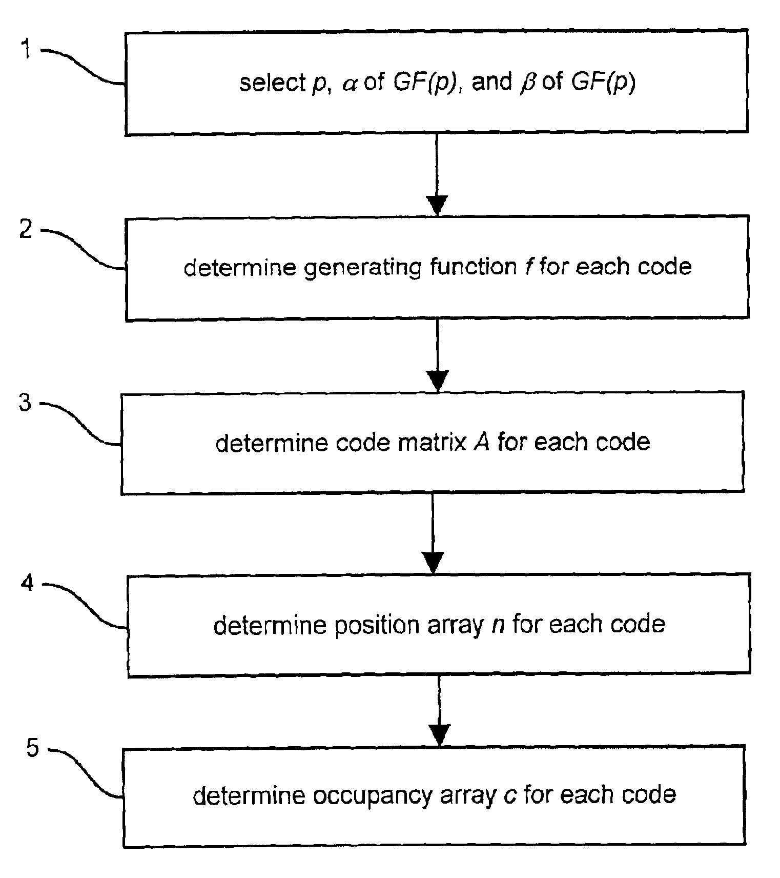
[0127]For block 1, select p=5, α=2 of GF(5), and β=3 of GF(5), verifying the primitivity of α and β.

[0128]For block 2, the following generating functions are defined:

f(0)(x)=mod5(x2+x)

f(1)(x)=mod5(x2+x+1)

f(2)(x)=mod5(x2+x+2)

f(3)(x)=mod5(x2+x+3)

f(4)(x)=mod5(x2+x+4)

 f(5)(x)=mod5(x+1).

[0129]For block 3, a matrix A(k) is determined for each code k in the code family, where 0≦k≦5. Each matrix A(k) is based on the corresponding generating function f(k). FIG. 12 illustrates the code matrix A(k) for each code k in the code family. The values in the row above each matrix A(k) are the values of powers of α modulo 5 (i.e., mod5 (αj) for 0≦j≦3), and the column of values to the left of each matrix A(k) are the values of powers of β modulo 5 (i.e., mod5(βi) for 0≦i≦3).

[0130]For block 4, a position array P(k) is determined for each code k in the code family. For example, for code 0 and code 1, the position arrays are:

P(0)=[0, 0, 0, 3, 4, 0, 0, 0, 0, 0, 0, 0, 0, 0, 15]

P(1)=[0, 1, 0, 0, 0, 0, 0, 7, ...

example 2

[0132]In Example 2, a larger code cycle is generated than in Example 1. For block 1, the following are selected: p=29, which results in a Galois field GF(29) having 12 primitive elements; α=21 of GF(29); and β=27 of GF(29) are chosen and verified to be primitive.

[0133]As per block 2, 30 generating functions may be defined. However, since the generation of only two codes is desired, generating functions for code 17 and code 26, which were selected arbitrarily for this example to illustrate control over the number of codes generated, are defined as follows:

f(17)(x)=mod29(x2+x+17)

f(26)(x)=mod29(x2+x+26).

[0134]After performing blocks 3 through 5, the occupancy arrays are generated for code 17 and code 26. The code cycle for each code has 28 (=p−1) components and 784 (=(p−1)2=(28)2) subcomponents, and each code has between 26 (=p−3) and 28 (=p−1) components containing signal portions within a subcomponent and between 0 and 2 components without a signal present. The occupancy arrays C(17)...

example 3

[0137]In Example 3, a slightly smaller code cycle than that of Example 2 is generated. As per block 1, the following are selected: p=23; α=19 of GF(23) and β=11 of GF(23), and 19 and 11 are verified as primitive in GF(23). Applying blocks 2 through 5, occupancy arrays C are generated for the 24 codes of the code family as shown in FIG. 15. Each row in FIG. 15 corresponds to one of the codes. The code cycle for each code has 484 (=(p−1)2=(22)2) subcomponents, and each code has either 20, 21 or 22 (p−3, p−2, or p−1) components containing signals within a subcomponent. FIG. 15 also illustrates the code compression aspect of the current invention, where several of the 24 codes of the code family can be seen to be shorter than the others due to the occupancy array method of representing them.

[0138]FIG. 16 illustrates the maximum correlation values between the 24 codes in the code family. The code values are illustrated in the form of a 24×24 matrix. The elements on the main diagonal of t...


PUM


Abstract

The present invention relates to a method for generating and apparatus for employing code families having desirable correlation properties. Regardless of code length, maximum autocorrelation of the codes is 4 for any nonzero offset and maximum cross-correlation of any two codes from a code family is 4 for any offset. The codes can be used in impulse radio systems and non-impulse radio systems including CDMA, TDMA, FDMA, OFDM and various other frequency hopping and direct sequence systems. The codes can be used to specify various impulse radio and non-impulse radio signal characteristics including pulse position in time, amplitude, width, type, phase, phase difference, frequency, spreading code, etc. The codes have the unique property that they can specify as many as two components in which a signal is not present. A method of code compression is provided.

Description

CROSS-REFERENCE TO OTHER APPLICATIONS[0001]The following applications of common assignee may contain common disclosure with the present application:[0002]U.S. patent application Ser. No. 09 / 638,192 entitled “A METHOD FOR SPECIFYING NON-TEMPORAL PULSE CHARACTERISTICS”, filed on Aug. 15, 2000.[0003]U.S. patent application Ser. No. 09 / 638,046 entitled “A METHOD AND APPARATUS FOR APPLYING CODES HAVING PREDEFINED PROPERTIES”, filed on Aug. 15, 2000.[0004]U.S. patent application Ser. No. 09 / 637,878 entitled “A METHOD AND APPARATUS FOR POSITIONING PULSES USING A LAYOUT HAVING NON-ALLOWABLE REGIONS”, filed on Aug. 15, 2000.[0005]U.S. patent application Ser. No. 09 / 638,150 entitled “A METHOD AND APPARATUS FOR POSITIONING PULSES IN TIME”, filed on Aug. 15, 2000.[0006]U.S. patent application Ser. No. 09 / 638,151 entitled “A METHOD AND APPARATUS FOR MAPPING PULSES TO A NON-FIXED LAYOUT”, filed on Aug. 15, 2000.[0007]U.S. patent application Ser. No. 09 / 638,152 entitled “A METHOD AND APPARATUS FOR...

Claims


Application Information

Patent Timeline
IPC IPC(8): H04J13/00H04B1/69H04J13/10
CPCH04J13/00H04J13/10
Inventor KUMAR, P. VIJAYPENDERGRASS, MARCUS H.
Owner TIME DOMAIN
Why Eureka
Try Eureka