Clock signal transmitting system, digital signal transmitting system, clock signal transmitting method, and digital signal transmitting method
a clock signal and transmitting system technology, applied in the field of clock signal transmitting system, digital signal transmitting system, clock signal transmitting method, digital signal transmitting method, can solve the problems of data signal transmitted through a transmission path radiating electromagnetic noise at these frequencies, video signal and audio signal which have been band-compressed have a high entropy, etc., to achieve a simple circuit and suppress electromagnetic noise. radiated
- Summary
- Abstract
- Description
- Claims
- Application Information
AI Technical Summary
Benefits of technology
Problems solved by technology
Method used
Image

Examples
first embodiment
[0057][First Embodiment]
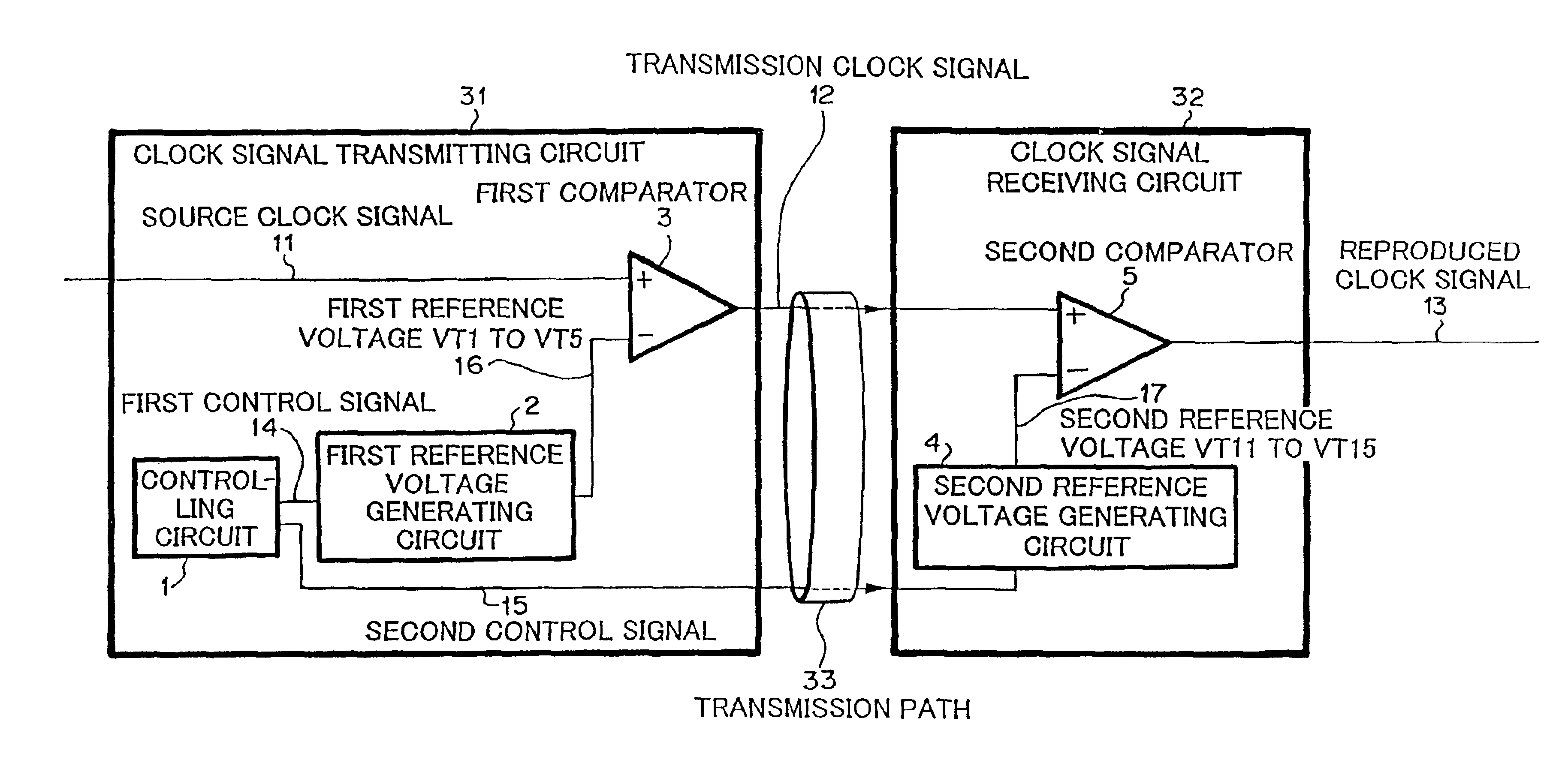
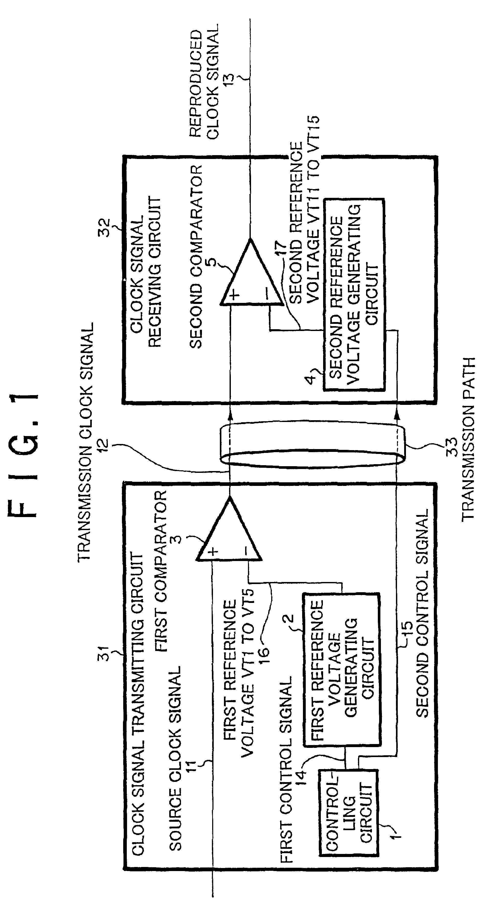
[0058]First of all, with reference to FIG. 1, the structure of a clock signal transmitting system according to a first embodiment will be explained.
[0059]Referring to FIG. 1, the clock signal transmitting system according to the first embodiment comprises clock signal transmitting circuit 31 and clock signal receiving circuit 32.
[0060]Clock signal transmitting circuit 31 comprises controlling circuit 1, first reference voltage generating circuit 2, and first comparator 3. Controlling circuit 1 generates first control signal 14 and second control signal 15. First control signal 14 and second control signal 15 are used to periodically vary first reference voltage 16 and second reference voltage 17, respectively, and to synchronize voltages 16 and 17. First reference voltage generating circuit 2 determines first reference voltage 16 corresponding to first control signal 14 and outputs first reference voltage 16. First comparator 3 inputs source clock signal 11 a...
second embodiment
[0090][Second Embodiment]
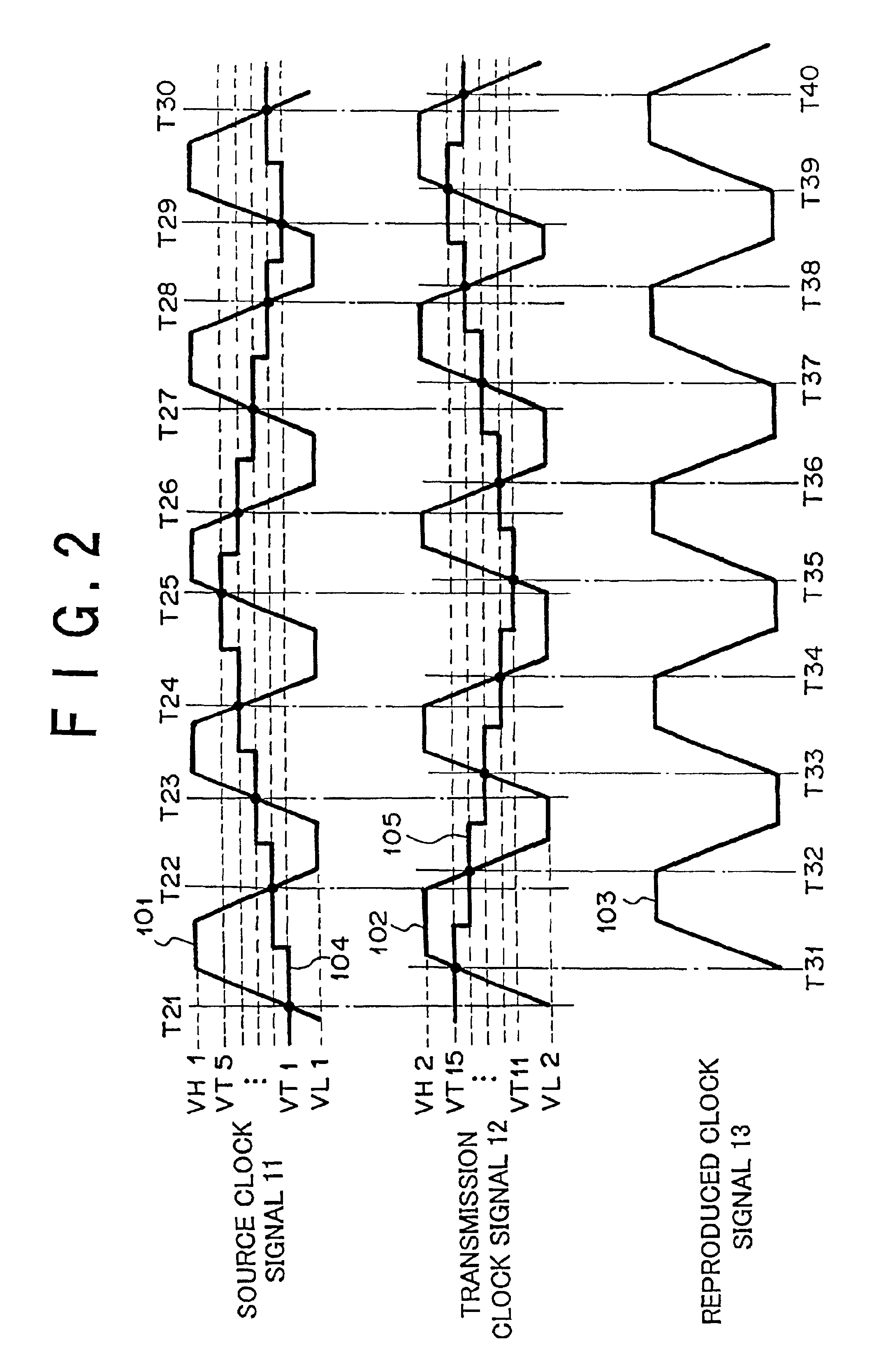
[0091]According to a second embodiment of the present invention shown in FIG. 8, controlling circuit 1 inputs source clock signal 11 and detects the timing at which the voltage level of the waveform of source clock signal 11 becomes VH1 and the timing at which the voltage level of the waveform of source clock signal 11 becomes VL1. Corresponding to these timings, controlling circuit 1 generates first control signal 14 and second control signal 15. This operation is based on the principle that when the voltage level of source clock signal 11 is varied, the voltage levels of first reference voltage 16 and second reference voltage 17 should be varied. First control signal 14 is output whenever the voltage level of the waveform of source clock signal 11 becomes VH1 or VL1. Alternatively, first control signal 14 is output every time when one or more period of first reference voltage 16 and second reference voltage 17 elapse. Second control signal 15 is output eve...
third embodiment
[0095][Third Embodiment]
[0096]According to a third embodiment of the present invention shown in FIG. 11, controlling circuit 1 inputs transmission clock signal 12, detects the timings at which the voltage level of the waveform of transmission clock signal 12 becomes VH2 and the timings at which the voltage level of the waveform of transmission clock signal 12 becomes VL2, and generates first control signal 14 and second control signal 15 corresponding to these detection timings. This operation is based on the principle that when the voltage level of transmission clock signal 12 is varied, the voltage level of the second reference voltage 17 may be varied and the voltage level of first reference voltage 16 may be varied. It is not too late to vary the voltage of first reference voltage 16 when the voltage level of transmission clock signal 12 is changed. First control signal 14 is output whenever the voltage level of the waveform of source clock signal 11 becomes VH1 or VL1. Alternat...
PUM
 Abstract
Description
Claims
Application Information
 - R&D
- Intellectual Property
- Life Sciences
- Materials
- Tech Scout
- Unparalleled Data Quality
- Higher Quality Content
- 60% Fewer Hallucinations
Browse by: Latest US Patents, China's latest patents, Technical Efficacy Thesaurus, Application Domain, Technology Topic, Popular Technical Reports.
© 2025 PatSnap. All rights reserved.Legal|Privacy policy|Modern Slavery Act Transparency Statement|Sitemap|About US| Contact US: help@patsnap.com