Shared bypass bus structure

a bus structure and bypass technology, applied in the field of processor systems, can solve the problems of increasing snoop latency, high cost and power sensitive front-end and departmental servers, and reducing the efficiency of the system

Inactive Publication Date: 2005-06-28
INTEL CORP
View PDF8 Cites 107 Cited by
  • Summary
  • Abstract
  • Description
  • Claims
  • Application Information

AI Technical Summary

Problems solved by technology

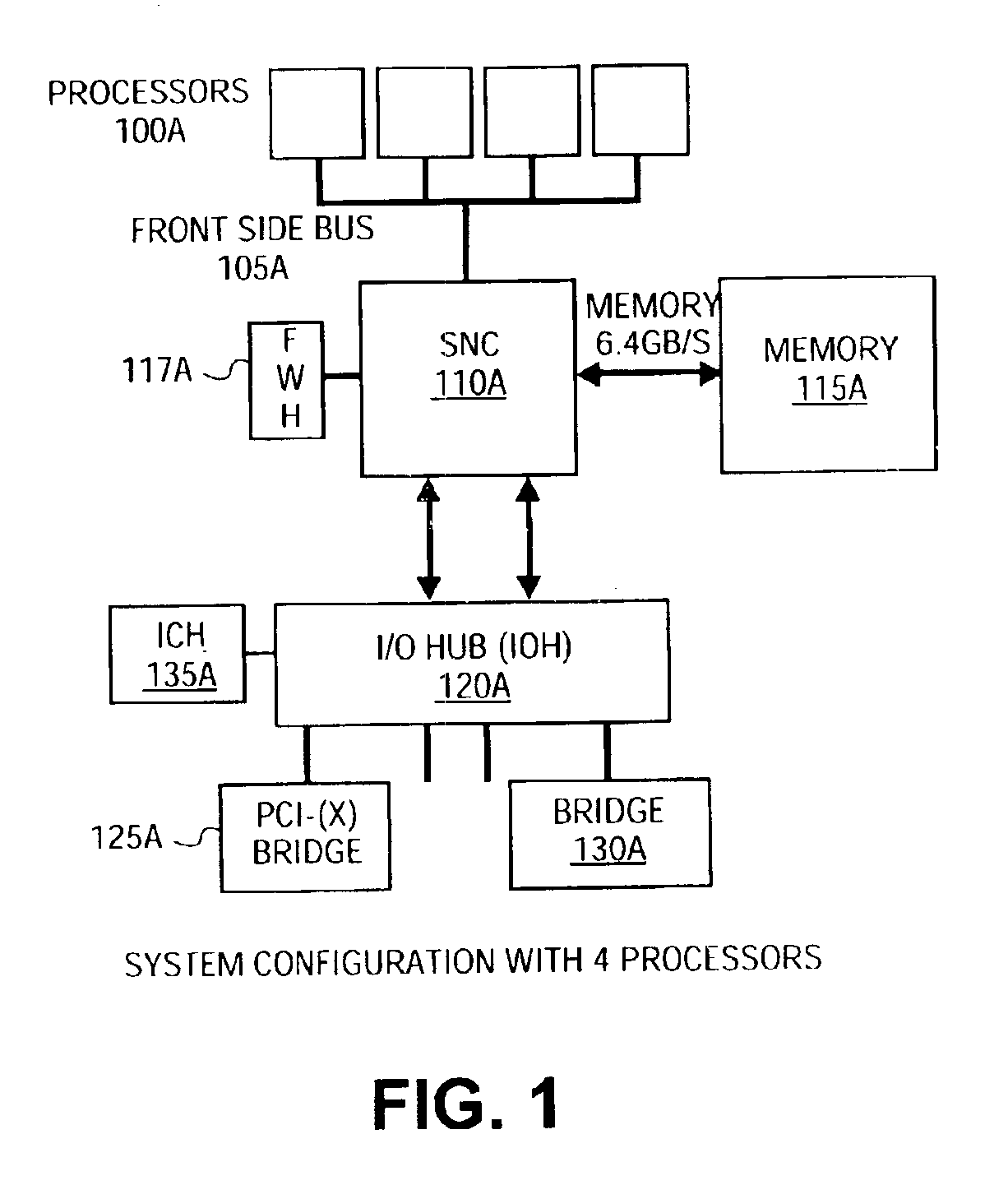
Front-end and departmental servers are very cost and power sensitive while back-end servers that traditionally run database type applications require the highest level of performance along with multi-dimensional scalability and 24×7 availability.
Further, current systems provide a single path for cache coherency operations and data transfer, causing cache coherency transactions to wait for data transfers, increasing snoop latency.
Coherent transactions limit the bandwidth for transactions from a peripheral input-output (I/O) bus in processor-based systems such as desktop computers, laptop computers and servers.
When the I/O devices may count on the ordering of transactions, I/O devices may issue transactions that would otherwise cause unpredictable results.
However, the host bus may be an unordered domain that does not guaranty that transactions are carried out in the order received from the PCI

Method used


Image

  • Shared bypass bus structure
  • Shared bypass bus structure
  • Shared bypass bus structure

Examples


Embodiment Construction

[0027]In the following description, numerous specific details are set forth. However, it is understood that embodiments of the invention may be practiced without these specific details. In other instances, well-known circuits, structures and techniques have not been shown in detail in order not to obscure an understanding of this description. References to “one embodiment”, “an embodiment”, “example embodiment”, “various embodiments”, etc., indicate that the embodiment(s) of the invention so described may include a particular feature, structure, or characteristic, but not every embodiment necessarily includes the particular feature, structure, or characteristic. Further, repeated use of the phrase “in one embodiment” does not necessarily refer to the same embodiment, although it may. In various places, multiple copies of an item are referred to with the designation “A”, “B”, “C”, etc. Any characteristics attributed to any one of the designated items (e.g., item 120A) may also be att...


PUM


Abstract

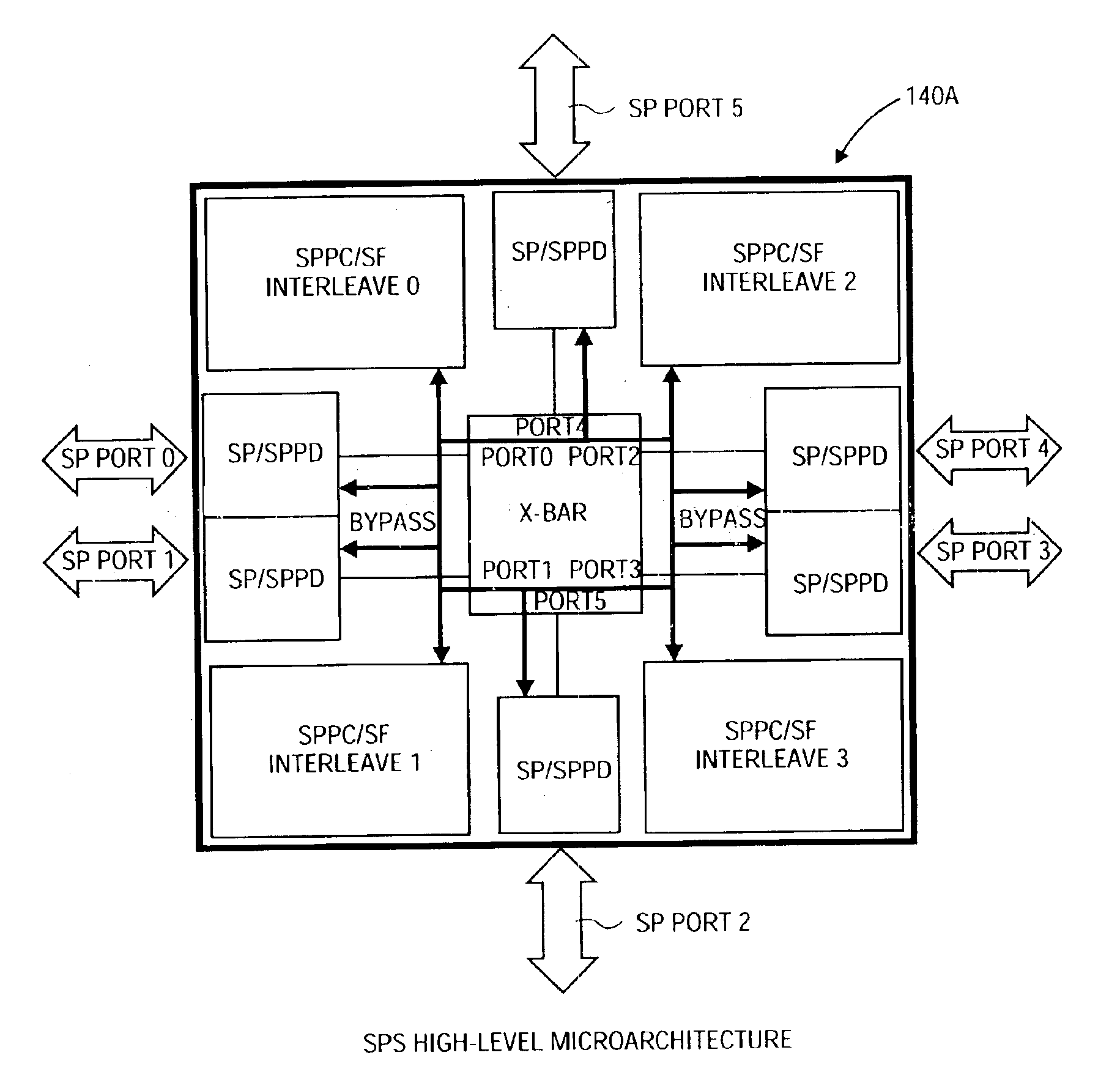
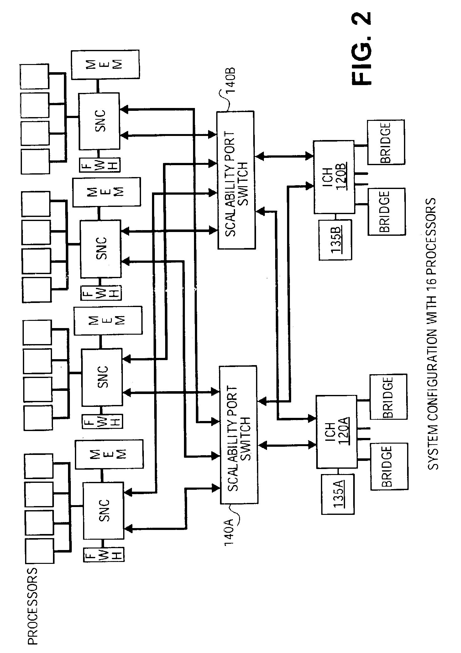
A shared bypass bus structure for low-latency coherency controller access in a coherent scalable switch. In a coherent scalable switch with multiple coherent interconnect ports, distributed coherency control structures, and a crossbar interface between them, a shared bypass bus permits data transfer between the coherent interconnect ports and the coherency control structures while bypassing the crossbar interface. Some embodiments may comprise scalable switches to support one or more sets of processors with substantially independent snoop or cache coherency paths or arrangements.

Description

CROSS REFERENCE TO RELATED APPLICATIONS[0001]This application claims priority of the filing date of co-pending U.S. provisional application 60 / 359,316, filed Feb. 25, 2002.BACKGROUND[0002]1. Technical Field[0003]An embodiment of the invention pertains generally to processor systems, and in particular pertains to scalable processor systems.[0004]2. Description of the Related Art[0005]With the rapid evolution of the Internet requirements for enterprise server systems have become increasingly diverse. Front-end and departmental servers are very cost and power sensitive while back-end servers that traditionally run database type applications require the highest level of performance along with multi-dimensional scalability and 24×7 availability. This segmentation of the server platforms has led to the development of a multitude of chipsets. A chipset encompasses the major system components that move data between the main memory, the processor(s) and the I / O devices. System vendors have d...

Claims


Application Information

Patent Timeline
IPC IPC(8): G06F12/08G06F12/00
CPCG06F12/0813G06F12/0862G06F12/082G06F12/0833
Inventor KAPUR, SUVANSH K.CHENG, KAIHOOGLAND, ROBERT J.
Owner INTEL CORP
Why Eureka
Try Eureka