
Wiring fault detection, diagnosis and reporting for process control systems

a technology for process control systems and wiring faults, applied in fault response, data switching networks, instruments, etc., can solve the problems of one or more bus wires being improperly terminated, one or more bus wires being severed or shorted to another wire, and the difficulty of detecting, diagnosing and reporting wiring faults within a segment is typically very large, so as to achieve efficient and convenient

Inactive Publication Date: 2005-06-28
FISHER-ROSEMOUNT SYST INC
View PDF5 Cites 67 Cited by
  • Summary
  • Abstract
  • Description
  • Claims
  • Application Information

AI Technical Summary

Benefits of technology

[0010]A wiring fault detection, diagnostic and reporting technique enables linking devices (i.e., the interfaces between smart field devices and controllers) within a process control system to measure the electrical characteristics of a segment protocol bus and the signals transmitted via the protocol bus. The technique described herein also enables the linking devices to analyze the measured electrical characteristics to determine whether a wiring fault exists on a protocol bus connected to that linking device. Additionally, the technique described herein enables the linking devices to report the wiring fault information such as electrical characteristic information, signal quality information, diagnostic information, etc. to respective controllers which, in turn, may automatically report this wiring fault information to a user via a user interface. In this manner, the wiring fault detection, diagnostic and reporting technique described herein enables a user to perform commissioning activities such as, for example, wiring check outs, in an efficient and convenient manner from an operator's terminal, thereby reducing or eliminating the need for a field technician to physically inspect every segment throughout the process control system, as is required with current systems.

Problems solved by technology

While the protocol bus wiring for the multitude of segments that are typically used within a distributed process control system is being installed, one or more bus wires may be inadvertently connected to the wrong terminal (i.e., the wrong signal port, power supply voltage, etc.), one or more bus wires may be left unconnected (i.e., an open-circuit condition), and / or one or more bus wires may be improperly terminated.
Additionally, even if all protocol bus wiring is initially installed properly, one or more of the bus wires may become severed or shorted to another wire or potential (e.g., a voltage source, ground line, etc.) during subsequent operation of the process control system.
Detecting, diagnosing and reporting a wiring fault within a segment is typically very difficult because current linking devices cannot measure or analyze the electrical characteristics such as the resistance, capacitance, etc. of the segment protocol bus or the amplitude, frequency, noise level, etc. of the signals being transmitted via the segment protocol bus.
As a result, users at the system level (e.g., at an operator's terminal having a graphical user interface) cannot easily identify a wiring fault on a particular segment and are typically only informed by the system that the overall process is not operating properly and / or that a communication error has occurred.
However, the controller typically does not provide the user with any additional information that could be used to determine why the devices failed to respond.
In fact, neither the controller nor the linking device can measure the resistance of the bus wires to detect the shorted condition, thereby preventing the detection and reporting of such a wiring fault.
Thus, with existing systems, a field technician typically does not have any information, other than that a communication problem exists, indicating on which segment the wiring fault has occurred or what type of wiring fault is likely to have caused the communication problem.

Method used


Image

  • Wiring fault detection, diagnosis and reporting for process control systems
  • Wiring fault detection, diagnosis and reporting for process control systems
  • Wiring fault detection, diagnosis and reporting for process control systems

Examples


Embodiment Construction

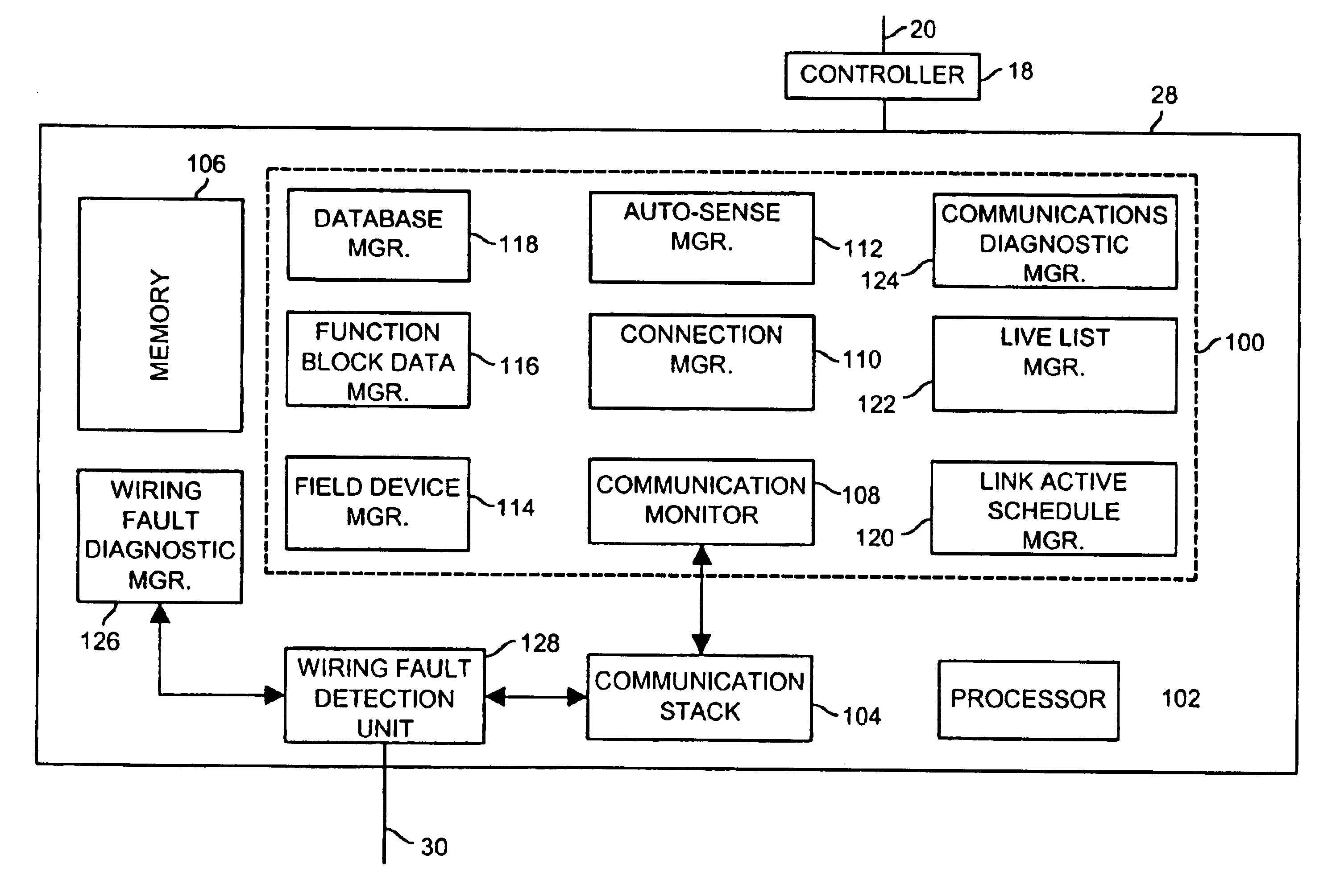
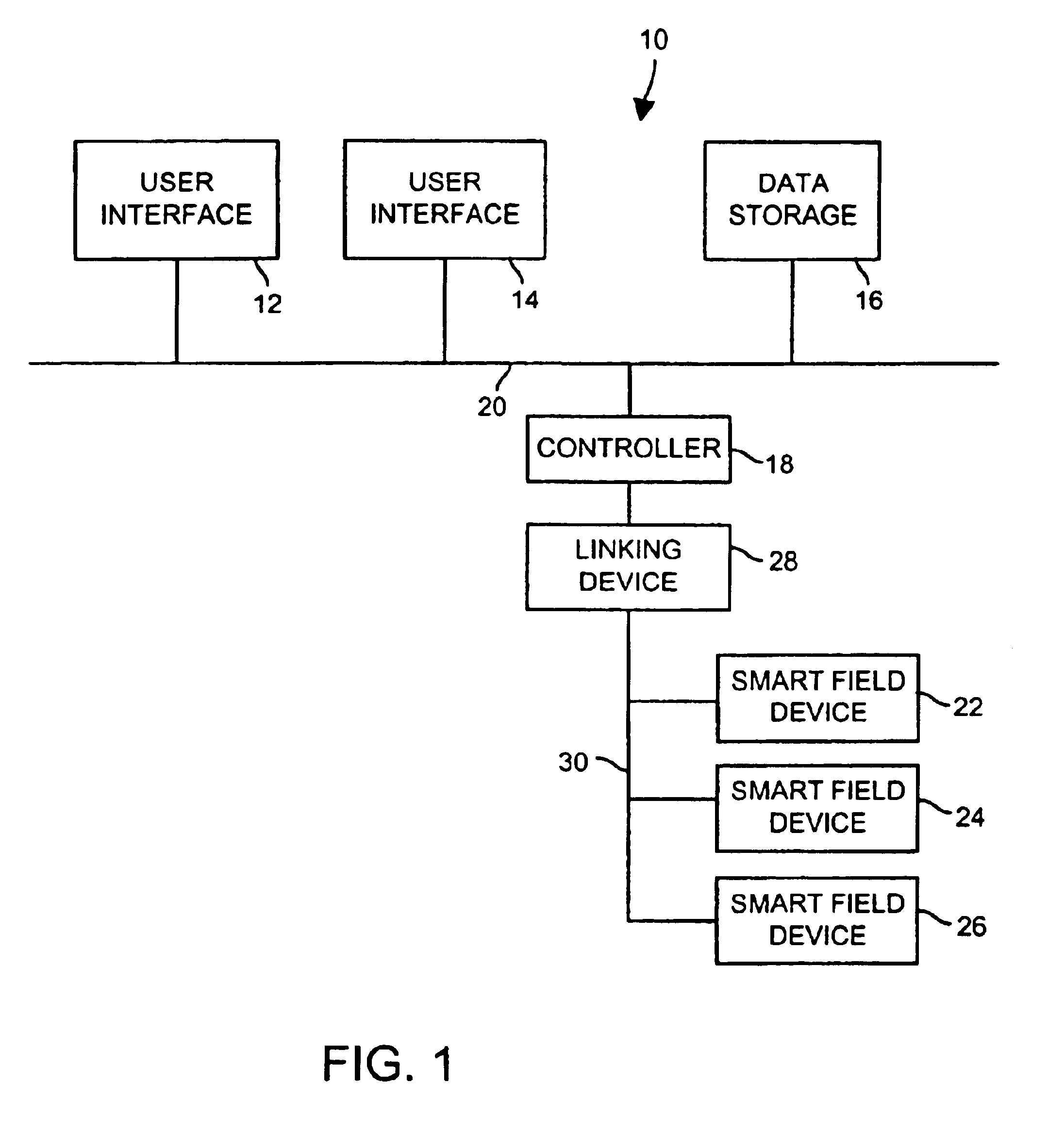
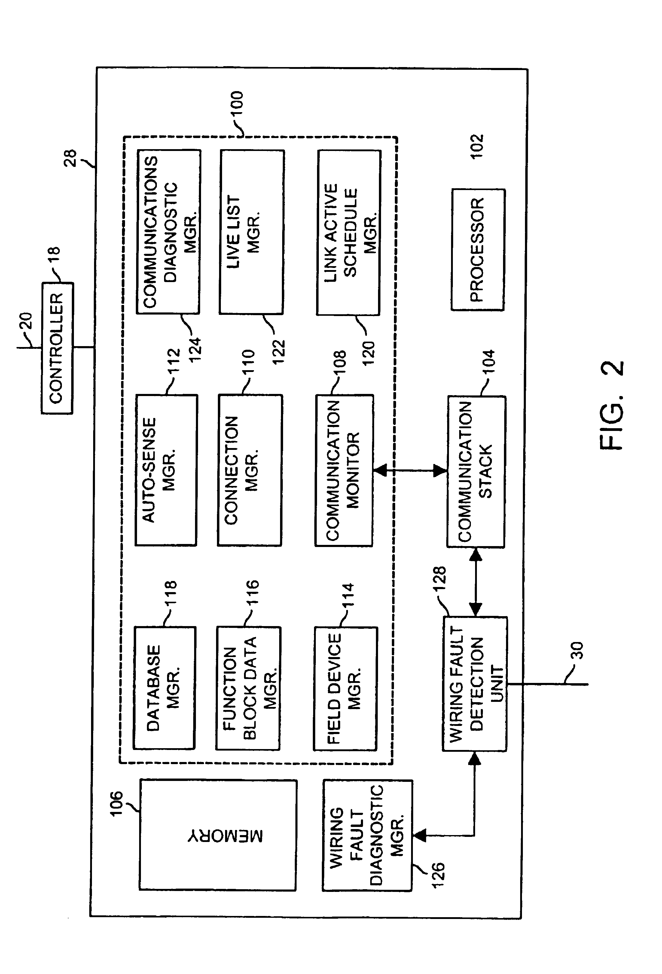
[0019]While a technique for detecting, diagnosing and reporting wiring faults within a distributed process control system is described in detail in conjunction with a process control system that implements process control functions using Fieldbus devices, the wiring fault detection, diagnosis and reporting technique described herein may be used with process control systems that perform control functions using other types of field devices and communication protocols, including protocols that rely on other than two-wire buses and protocols that support only analog or both analog and digital communications, such as those mentioned previously.

[0020]The Fieldbus protocol is an all-digital, serial, two-way communication protocol that provides a standardized physical interface to a two-wire loop or bus interconnecting field equipment such as sensors, actuators, controllers, valves, etc. located in an instrumentation or process control environment of, for example, a factory or a plant. The ...


PUM


Abstract

A wiring fault detection, diagnostic and reporting technique enables linking devices within a process control system to measure the electrical characteristics of a segment protocol bus and the electrical characteristics of the signals transmitted via the protocol bus. The technique connects a signal line of a segment protocol bus to one of a plurality of measurement blocks within a wiring fault detection unit. The one of the plurality of measurement blocks measures an electrical characteristic associated with the segment protocol bus and sends the measured electrical characteristic to a wiring fault diagnostic manager. The wiring fault diagnostic manager analyzes the measured electrical characteristic to determine a type of the wiring fault and reports the type of the wiring fault via a user interface.

Description

FIELD OF THE INVENTION[0001]The present invention relates generally to process control systems and, more specifically, to automatically detecting, diagnosing and reporting wiring faults within communication segments of a process control system.DESCRIPTION OF THE RELATED ART[0002]Modern process control systems are typically microprocessor-based distributed control systems (DCSs). A traditional DCS configuration includes one or more user interface devices, such as workstations, connected by a databus (e.g., Ethernet) to one or more controllers. The controllers are generally located physically close to a controlled process and are connected to numerous electronic monitoring devices and field devices such as electronic sensors, transmitters, current-to-pressure transducers, valve positioners, etc. that are located throughout the process.[0003]In a traditional DCS, control tasks are distributed by providing a control algorithm within each of the controllers. The controllers independently...

Claims


Application Information

Patent Timeline
IPC IPC(8): H04L29/14H04L12/423G06F11/07G06F11/30G05B23/02H04L69/40
CPCG06F11/0736G06F11/079G06F11/3013H04L69/40G06F11/3055H04L12/423G06F11/3041
Inventor CHRISTENSEN, DANIEL DBONWELL, STEVEN D.MARSHALL, MICHAEL L.
Owner FISHER-ROSEMOUNT SYST INC
Features
  • Generate Ideas
  • Intellectual Property
  • Life Sciences
  • Materials
  • Tech Scout
  • Unparalleled Data Quality
  • Higher Quality Content
  • 60% Fewer Hallucinations
Learn More