Method, computer program and control and/or regulating appliance for operating an internal combustion engine, and corresponding internal combustion engine

a technology for internal combustion engines and computer programs, applied in the direction of electrical control, process and machine control, instruments, etc., can solve problems such as non-optimal mixtures in combustion chambers, and achieve the effect of improving the operational performance of internal combustion engines, especially fuel consumption

Inactive Publication Date: 2005-07-05
ROBERT BOSCH GMBH
View PDF9 Cites 19 Cited by
  • Summary
  • Abstract
  • Description
  • Claims
  • Application Information

AI Technical Summary

Benefits of technology

[0009]In this way, the depth of penetration of the fuel drops in such an injection pulse. In this way, it is prevented that the fuel, which is injected into the combustion chamber with an injection pulse, impinges against the wall lying opposite to the injection valve and leads to the wall application mentioned initially herein. The shorter the duration of the injection pulse, the more it is ensured that the fuel injected in this way mixes with the air disposed in the combustion chamber and does not deposit on the wall of the combustion chamber. In the method of the invention, no continuous injection therefore takes place, rather, a pulsed injection takes place which is also characterized as a chopped injection.
[0022]The present invention further relates to an internal combustion engine having at least one combustion chamber and a device which injects the fuel directly into the combustion chamber. In order to improve the operational performance of this engine, especially the fuel consumption, the emission performance as well as the cold start performance, it is suggested in accordance with the invention that the engine be provided with a control apparatus (open loop and / or closed loop) of the above-mentioned type.

Problems solved by technology

However, a layer on the wall of the combustion chamber comprising fuel can be vaporized only with difficulty and therefore leads to a non-optimal mixture in the combustion chamber.

Method used


Image

  • Method, computer program and control and/or regulating appliance for operating an internal combustion engine, and corresponding internal combustion engine
  • Method, computer program and control and/or regulating appliance for operating an internal combustion engine, and corresponding internal combustion engine
  • Method, computer program and control and/or regulating appliance for operating an internal combustion engine, and corresponding internal combustion engine

Examples


Embodiment Construction

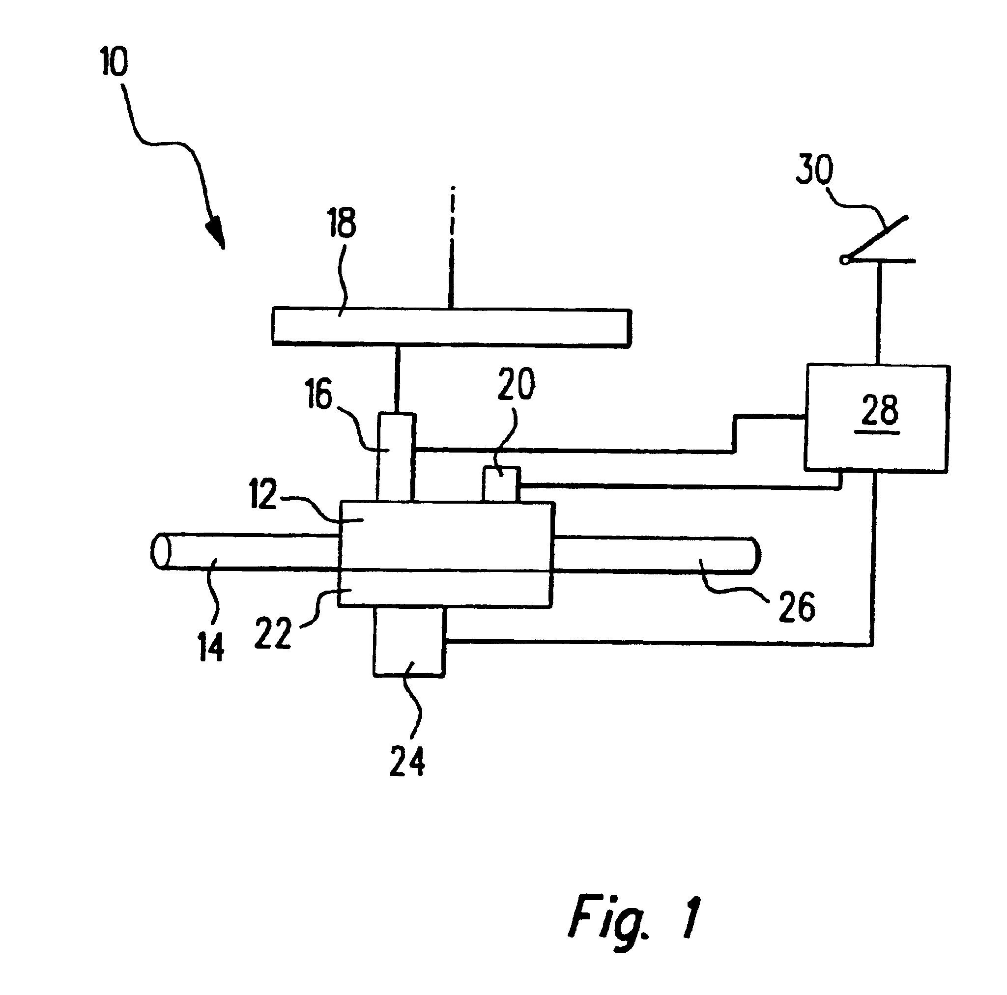
[0031]In FIG. 1, an internal combustion engine is identified by reference numeral 10. Typically, the engine is operated in accordance with the four-stroke principle and a work cycle therefore includes four strokes. Such an engine is, for example, used in motor vehicles. The engine includes a combustion chamber 12 to which air is supplied via an intake manifold 14. Fuel is injected into the combustion chamber 12 via a high pressure injection valve 16. This injection valve is fed from a fuel collection line 18 which is also characterized as a “rail” and in which the fuel is made available under very high pressure. The ignition of the air / fuel mixture, which is formed in the combustion chamber 12, takes place via an ignition device 20, preferably, a spark plug. A piston 22 is moved by the expansion of the combusting air / fuel mixture. The operating state of the internal combustion engine 10, especially the position of the piston 22, is detected by a sensor 24. The hot combustion exhaust...


PUM


Abstract

An internal combustion engine (10), especially of a motor vehicle, is operated with a method wherein the fuel is injected directly into a combustion chamber (12) of the internal combustion engine (10) with at least one injection (36) per work cycle. In order to reduce the fuel consumption and to improve the emission performance of the internal combustion engine (10), it is suggested that a fuel injection (36) includes a plurality of short injection pulses (32) spaced in time from each other.

Description

[0001]This application is the U.S. national stage of international application No. PCT / DE 02 / 00394, filed Feb. 4, 2002, designating the United States.FIELD OF THE INVENTION[0002]The present invention relates to a method for operating an internal combustion engine, especially of a motor vehicle wherein the fuel is injected directly into a combustion chamber of the engine with at least one injection per work cycle.BACKGROUND OF THE INVENTION[0003]A method of this kind is known from the marketplace. The method is also known as gasoline direct injection. In this method, the fuel is injected into the combustion chamber of the engine at very high pressure via injection valves mounted directly at the combustion chamber. The engine operates cyclically. In a four-stroke internal combustion engine, a work cycle includes, for example, four work strokes.[0004]In the known method, it was, however, determined that the total injected fuel does not always combust optimally. In some operating states...

Claims


Application Information

Patent Timeline
Patent Type & Authority Patents(United States)
IPC IPC(8): F02D41/40F02B75/00F02B75/12F02D41/34
CPCF02D41/402F02B2075/125F02D2041/389Y02T10/44Y02T10/123Y02T10/12Y02T10/40
Inventor HERDEN, WERNER
Owner ROBERT BOSCH GMBH
Why Eureka
Try Eureka