Lightweight speaker enclosure

a speaker enclosure and light weight technology, applied in the field of speaker enclosures, can solve the problems of reducing affecting the sound performance of the speaker,

Inactive Publication Date: 2005-07-05
SOUTHERN CALIFORNIA SOUND IMAGE
View PDF12 Cites 27 Cited by
  • Summary
  • Abstract
  • Description
  • Claims
  • Application Information

AI Technical Summary

Benefits of technology

[0011]The aforementioned needs are satisfied by the sound speaker enclosure of the present teachings which generally includes a three-layer box section formed of an outer skin of a rigid material, a middle layer of a sound absorbing material, and an inner skin of a rigid material; and a baffle section that includes...

Problems solved by technology

A significant drawback of conventional speaker enclosures is weight.
Generally, large speaker enclosures have to support the weight of the large speakers, and consequently, can be very heavy.
As a result, the heavier the speaker enclosure, the more difficult it is to move and support.
Another difficulty that results from constructing speaker enclosures from plywood is that these materials often degrade the sound performance of the speaker.
However, plywood has a tendency to vibrate in response to these inwardly travelling errant sound waves.
These errant vibrations can result in distortion of the sound produced by the speakers, including a retransmission of resonant sound waves that tend to magnify unwanted frequencies.
However, placing extraneous materials and objects inside the speaker enclosure results in degradation of the sound performance of the speaker.
Unfortunately, the proposed labor intensive fabrication processes are expensive and time consuming, which results in high manufacturing costs.
Moreover, speaker enclosure production is bottlenecked by the lengthy curing times required by the layers of materials used, thus drastically affect...

Method used


Image

  • Lightweight speaker enclosure
  • Lightweight speaker enclosure
  • Lightweight speaker enclosure

Examples


Embodiment Construction

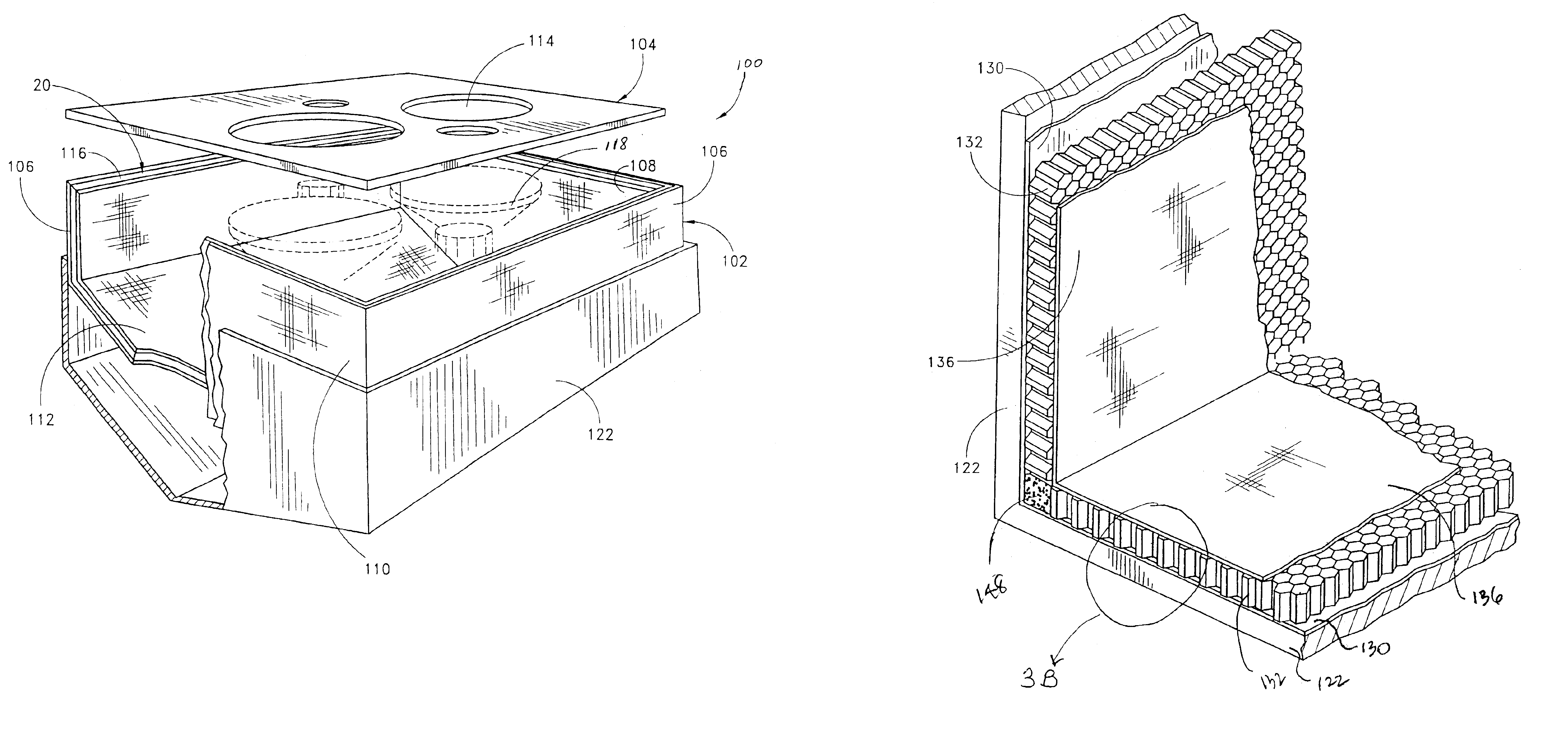
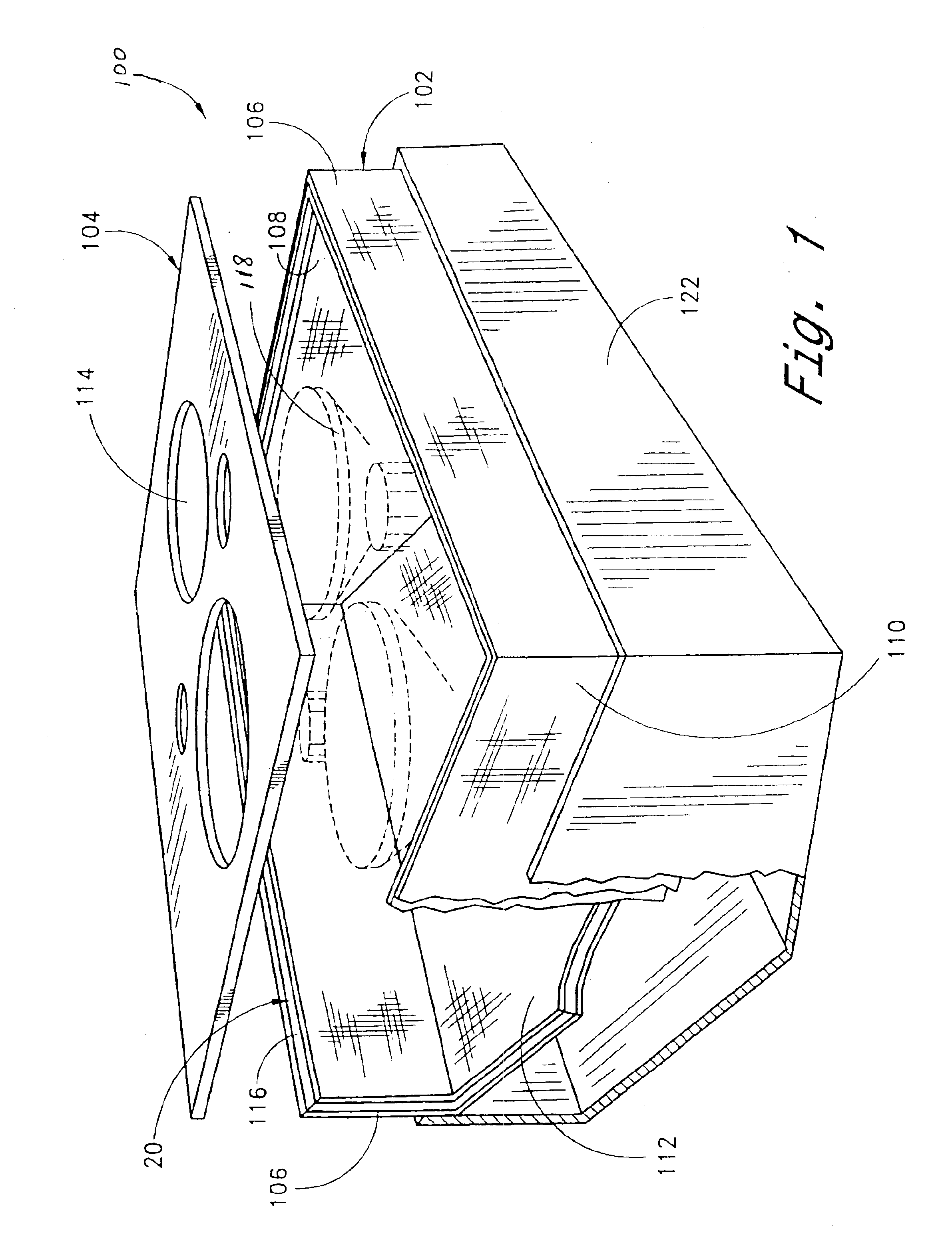
[0022]Reference will now be made to the drawings wherein like numerals refer to like parts throughout. FIG. 1 illustrates a speaker enclosure 100 according to one embodiment of the construction techniques described herein. The speaker enclosure 100 is comprised of two basic component parts, a box section 102 and a baffle section 104. The box section 102 defines a volume of space in which one or more speakers 118 (shown in phantom) are positioned. In an embodiment of the speaker enclosure 100 shown in FIG. 1, the box section 102 is shown to have a generally rectangular shape comprising opposing sidewalls 106, a top wall 108, a bottom wall 110, and a back wall 112. In one embodiment, the back wall 112 of the enclosure comprises two planar walls that extend from a back edge of each side wall, and form an obtuse angle at their intersection. The top and bottom walls 108, 110 are generally pentagonally shaped to achieve an open box configuration wherein the top, bottom, opposing side, and...


PUM

PropertyMeasurementUnit
Temperatureaaaaaaaaaa
Pressureaaaaaaaaaa
Capacitanceaaaaaaaaaa

Abstract

A speaker enclosure having a substantially seamless rigid outer skin, a middle sound absorbing layer, and a substantially seamless inner skin results in a lightweight speaker having sound absorbing characteristics. The speaker enclosure is comprised of two basic parts, a box section and a baffle section where each of these sections include a rigid outer skin, the middle sound absorbing layer and a seamless inner skin and are made according to the same method. The outer skin is formed from a layer of sheet molding compound, the middle sound absorbing layer includes pieces of honeycomb material, and the inner skin is formed from a layer of sheet molding compound. The layers of material are placed into a mold and then cured through vacuum bagging and heating thereby producing a strong, lightweight speaker enclosure made of materials which attenuate the transmission and retransmission of errant sound waves in the enclosure thereby reducing distortion of the sound signal produced by the speaker.

Description

RELATED APPLICATIONS[0001]This application claims the benefit of U.S. Provisional Application No. 60 / 401,431, filed Aug. 5, 2002, which is incorporated by reference in is entirety.BACKGROUND OF THE INVENTION[0002]1. Field of the Invention[0003]The present invention relates to speaker enclosures and, in particular, concerns a seamless speaker enclosure fabricated from lightweight, sound absorbing materials.[0004]2. Description of the Related Art[0005]Speaker enclosures are used in various applications ranging from home entertainment to music concerts. Conventional speaker enclosures are typically constructed from semi-rigid materials, such as plywood, and have a box-like shape. The front side of the speaker enclosure includes a baffle which has several openings in which the diaphragm portion of the speaker is positioned so that sound emanates from the speaker enclosure. A significant drawback of conventional speaker enclosures is weight. For example, large speakers used at music conc...

Claims


Application Information

Patent Timeline
IPC IPC(8): B29C65/00H04R1/02
CPCB29C70/088H04R1/02B29K2105/0097B29K2105/04B29K2105/06B29L2031/3418B29L2031/608B29K2995/0002
Inventor RITTO, ROSS
Owner SOUTHERN CALIFORNIA SOUND IMAGE
Why Eureka
Try Eureka