Disposable vacuum filtration apparatus capable of detecting microorganisms and particulates in liquid samples

a vacuum filter and liquid sample technology, applied in the field of filtration, can solve the problems of increasing production costs, not being able to easily position the lid, and not being able to mold parts to a dimension tolerance of 0.001′′, so as to achieve the effect of easy positioning the lid 611, reducing production costs, and reducing production costs

Inactive Publication Date: 2005-07-05
FOXX LIFE SCI
View PDF4 Cites 330 Cited by
  • Summary
  • Abstract
  • Description
  • Claims
  • Application Information

AI Technical Summary

Benefits of technology

[0101]Referring to FIG. 3c, if outer wall 623 of funnel 602 is smaller in diameter than inner wall 625 of base 601, to create gap 620, then the snap fit will be loose. If gap 620 is large enough, then funnel 602 will not snap fit into base 601, and thus funnel 602 will not be held in place by base 601. Referring to FIG. 3d, if outer wall 623 of funnel 602 is larger in diameter than inner wall 625 of base 601, to create overlap 629, then inner wall 625 of base 601 will stretch, (provided that the overlap is not to great) and the snap fit will fit properly. Although the snap fit shown in FIG. 3a, FIG. 3c, and FIG. 3d, provides for a greater value of dimension tolerance between funnel 602, and base 601, than the press fit described above for assembly 500, in production, with parts molded to a dimensional tolerance of ±0.003″, it may be necessary to match funnels to bases.
[0102]Referring to FIGS. 3a and 3b, lid 611 is press fitted onto the top of funnel 602 so that inner wall 614 of lid 611 engages outer wall 631 of funnel seal ring 630. Lid 611 should fit onto funnel 602 tightly enough so that it will not come loose, but not so a tight as to make it difficult for the user to remove lid 611 from funnel 602 with one hand. Lid 611 is normally molded from a rigid material such as polystyrene, and funnel 602 is normally molded from a more pliable material such as polypropylene. If lid 611, and funnel 602 are both molded with dimension tolerances of ±0.003″, and if under nominal conditions lid 611 press fits onto funnel 602 with 0.001″ of interference between inner wall 614 of lid 611, and outer wall 631 of funnel seal ring 630; then if the diameter of inner wall 614 of lid 611 is molded to its maximum dimension of nominal plus 0.003″, and if the diameter of outer wall 631 of funnel seal ring 630 is molded to its minimum dimension of nominal minus 0.003″, then lid 611 will not press fit onto funnel 602, instead there will be 0.005″ of slop between inner wall 614 of lid 611 and outer wall 631 of funnel seal ring 630, and lid 611 will fall off of funnel 602 if assembly 600 is accidentally tipped on its side. On the other hand if the diameter of inner wall 614 of lid 611 is molded to its minimum dimension of nominal minus 0.003″, and if the diameter of outer wall 631 of funnel seal ring 630 is molded to its maximum dimension of nominal plus 0.003″, then lid 611 will press fit onto funnel 602 with 0.007″ of interference between inner wall 614 of lid 611, and outer wall 631 of funnel seal ring 630. With this much interference it will not be possible to easily position lid 611 onto funnel 602 with one handed operation, nor will it be easy to remove lid 611 from funnel 602 with one handed operation.
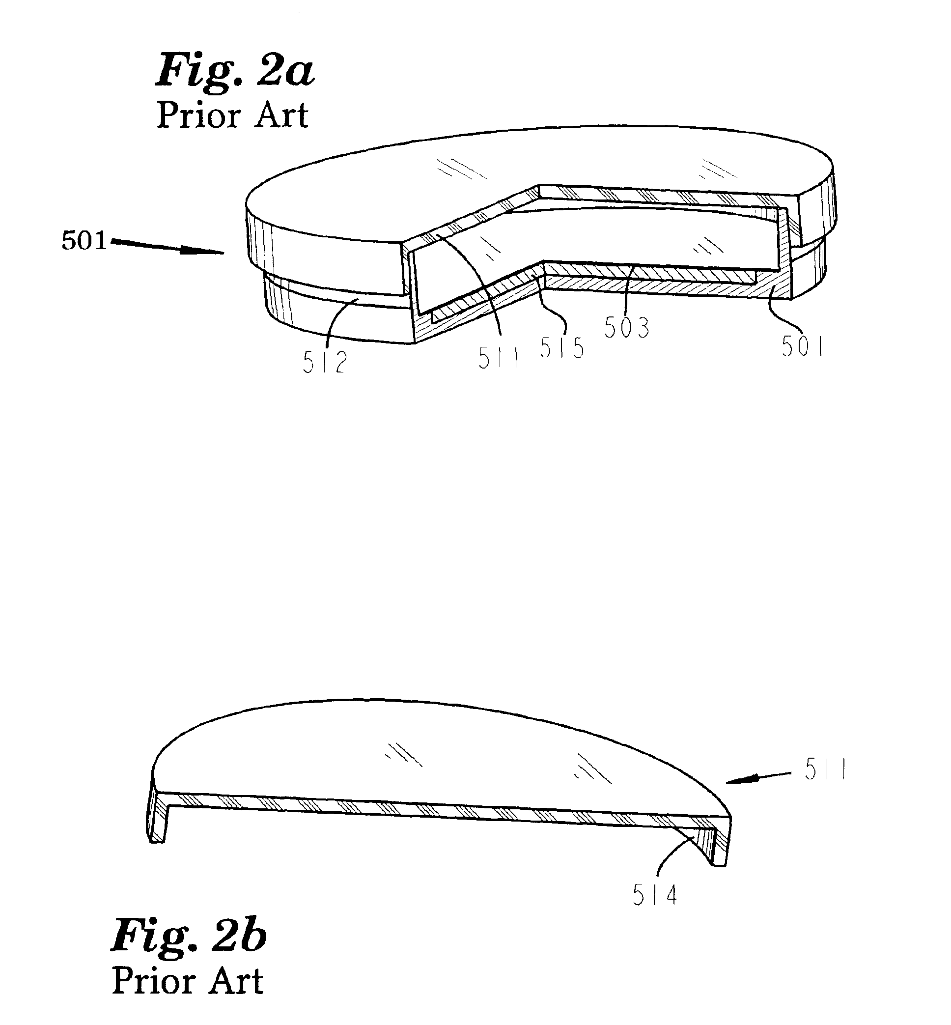
[0103]When filtration is complete, funnel 602 will be discarded, and lid 611 will be press fitted onto base 601 with inner wall 614 of lid 611 engaging outer wall 612 of base seal ring 632, to form a petri dish like the one shown in FIG. 2a. Lid 611 is normally molded from a rigid material such as polystyrene, and base 601 is normally molded from a more pliable material such as polypropylene. If lid 611, and base 601 are both molded with dimension tolerances of ±0.003″, and if under nominal conditions lid 611 press fits onto base 601 with 0.001″ of interference between inner wall 614 of lid 611, and outer wall 612 of base seal ring 632; then if the diameter of inner wall 614 of

Problems solved by technology

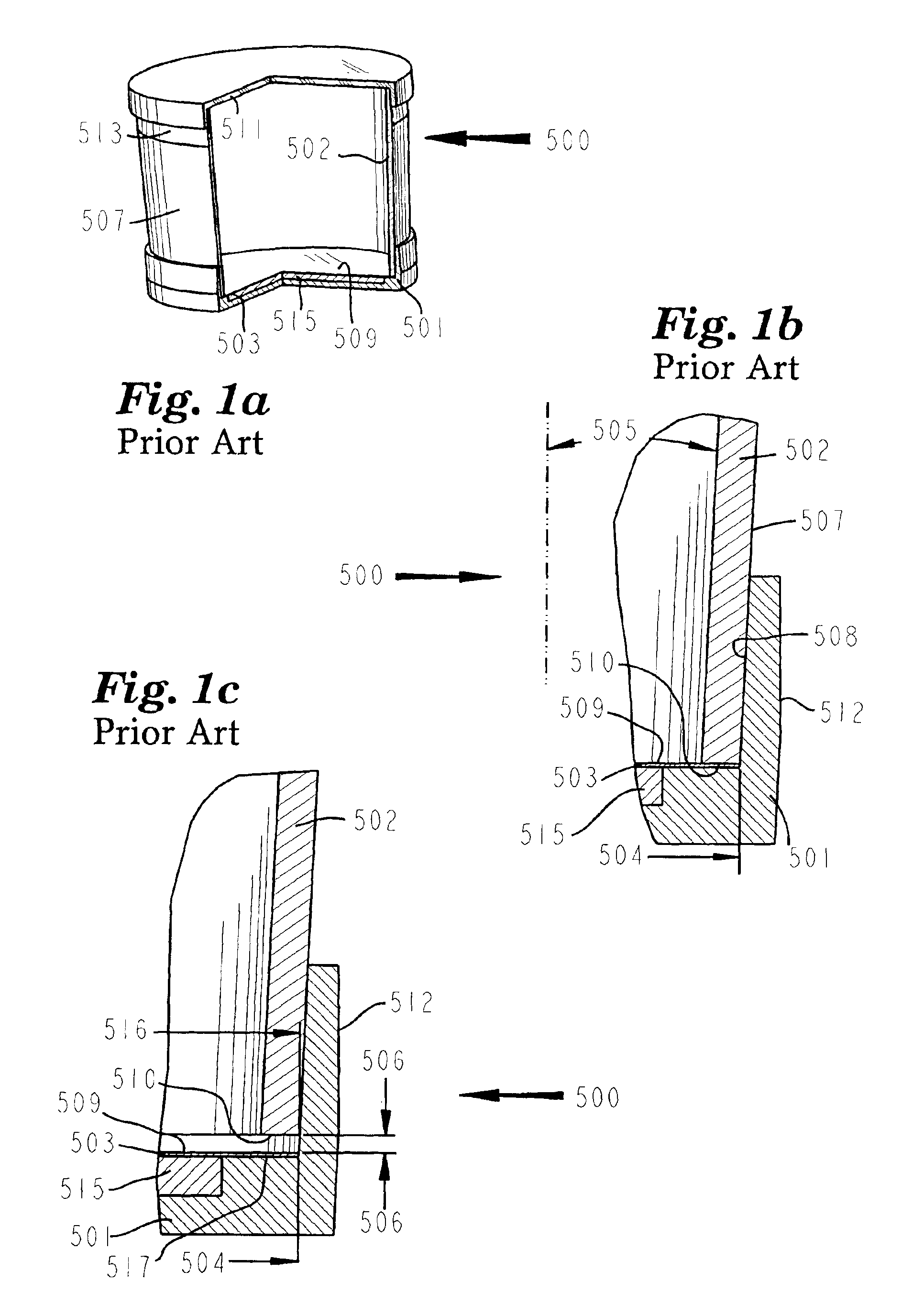
As explained above it is not practical to mold parts to a dimension tolerance of ±0.001″, or better.
This increases production costs, because of the time required to match parts, and because of the large amount of parts that have to be scrapped because they can no

Method used


Image

  • Disposable vacuum filtration apparatus capable of detecting microorganisms and particulates in liquid samples
  • Disposable vacuum filtration apparatus capable of detecting microorganisms and particulates in liquid samples
  • Disposable vacuum filtration apparatus capable of detecting microorganisms and particulates in liquid samples

Examples


first embodiment

[0122]An second embodiment of the filtration apparatus constructed in accordance with the principles of the present invention, is shown in FIG. 16. This embodiment shown as assembly 102 contains the same component parts as the first embodiment described above, with the exception that funnel 30 is replaced with funnel 130. The features of funnel 130 that are identical to those of funnel 30, have been given the same reference numbers as the corresponding feature of funnel 30. In addition to containing all of the features that funnel 30 contains, funnel 130 contains seal bead 180, which protrudes from bottom surface 44, of integral flexible filter seal 38. Although seal bead 180 as illustrated in FIG. 16 is circular in shape, it could be formed from any other shape such as rectangular, elliptical, ect. When funnel 130 is inserted into base 1, integral flexible filter seal 38 of funnel 130 will be compressed as explained above for funnel 30. Hence filter means 90 will be sealed between ...

third embodiment

[0123]the filtration apparatus constructed in accordance with the principles of the present invention, is shown in FIG. 17. Assembly 200 shown in FIG. 17 contains, base 201, funnel 30 (alternately funnel 130 could replace funnel 30), lid 60, filter means 90 (preferably a microporous filter), absorbent pad 91, and lower filter means 90a (preferably a microporous filter). Referring to FIG. 18 and FIG. 18a, base 201 contains funnel well 26, bounded by filter seal surface 11, and inside wall 5. Inside wall 5 contains chamber 20. Base 201 also contains a pad well 27, bounded by lower inside wall 8, and bottom inside surface 9. The outer edge of filter seal surface 11 contains groove 289. Base 201 contains outlet port 10. Bottom inside surface 9 may slope downward from its outside periphery toward outlet port 10. Outlet port 10 is in fluid flow communication with pad well 27. Base 201 also contains a means to support lower filter means 90a, shown here by circular filter support ribs 207, ...

sixth embodiment

[0130]the filtration apparatus constructed in accordance with the principles of the present invention, is shown in FIG. 24 through FIG. 28. FIG. 24 is an exploded view of assembly 700. Assembly 700 contains base 701, absorbent pad 791, filter means 90 (preferably a microporous filter), funnel 730, and lid 60. Base 701 is the same as base 201 shown in FIG. 18 with the exception that base 701 contains three or more filter centering tabs 779 (preferably equally spaced around the periphery of inside wall 705), and a counter bore defined by side wall 751, and chamber 753. Absorbent pad 791 is the same as absorbent pad 91 shown in FIG. 17, with the exception that absorbent pad 791 is thicker than absorbent pad 91. Absorbent pad 791 may be comprised of two or more thin layers of absorbent pad material. Funnel 730 is the same as funnel 30 shown in FIG. 8, FIG. 12, and FIG. 17, with the exception that funnel 730 contains funnel centering tabs 792. Although funnel 730 is shown with one integr...


PUM

PropertyMeasurementUnit
Angleaaaaaaaaaa
Thicknessaaaaaaaaaa
Forceaaaaaaaaaa

Abstract

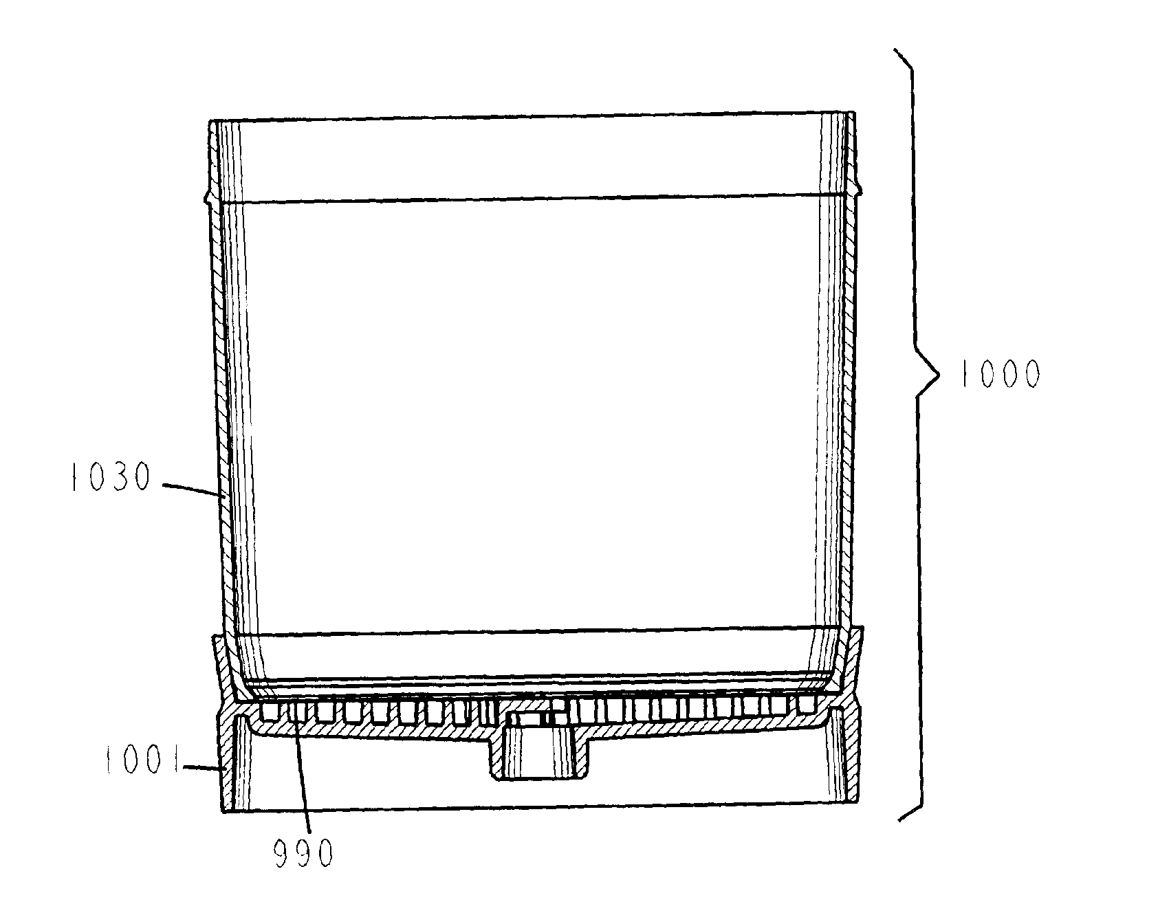
A vacuum filtration apparatus (900) for detecting microorganisms and particulates in liquid samples. The apparatus includes a base (901), an absorbent pad (991), a filter (990), a funnel (930), and a lid (960). The funnel is releasably attached to the base, and may contain an integral flexible seal for releasably sealing the filter to the base. The outer wall of the lid may be segmented to make it flexible, this flexibility allows it to be releasably attached to the funnel or the base. The apparatus is designed so that any funnel will fit any base, and any lid will fit any base or any funnel when all parts are manufactured to normal tolerances. The apparatus may be configured to to keep the filter wrinkle free in both the dry and wet states.

Description

[0001]This is a Continuation-in-Part of application Ser. No. 10 / 005,856, filed Dec. 4, 2001, now abandoned in which applicant claimed priority of Provisional Application No. 60 / 251,130, filed on Dec. 4, 2000, and of Provisional Application No. 60 / 297,832, filed on Jun. 12, 2001.BACKGROUND OF THE INVENTION[0002]This invention relates to the filtration field, and more particularly, to an improved disposable vacuum filtration apparatus capable of detecting microorganisms and particulates in liquid samples. There are commercially available disposable vacuum filtration devices for detecting microorganisms and particulates in liquid samples available today. The currently available disposable vacuum filtration devices for detecting microorganisms and particulates in liquid samples contain a base section, a removable funnel section, and a removable lid. An absorbent pad, and microporous filter are inserted into the base section. The absorbent pad is placed into a well in the base section, a...

Claims


Application Information

Patent Timeline
IPC IPC(8): B01D61/18B01D63/08B01L3/00B01D29/05B01D29/01G01N1/28G01N1/40
CPCB01D29/05B01D61/18B01D63/081B01D63/087B01L3/502G01N1/4077B01D29/085B01D2201/305B01D2201/34B01L2300/042B01L2300/0681B01L2300/0832B01L2400/049G01N1/40
Inventor ZUK, JR., PETER
Owner FOXX LIFE SCI
Why Eureka
Try Eureka