Self powered electronically controlled mixing valve

a technology of electronic control and self-powered valves, which is applied in the direction of valve operating means/release devices, process and machine control, instruments, etc., can solve the problems of inability to retrofit kits to reconfigure existing faucets with electronic controls, expensive expense, and inability to offer electronic faucets in “designers”

Inactive Publication Date: 2005-07-05
DELANGIS ERIC
View PDF6 Cites 103 Cited by
  • Summary
  • Abstract
  • Description
  • Claims
  • Application Information

AI Technical Summary

Benefits of technology

[0017]The invention is especially suited for retrofit applications where the electronic controls can be added to an existing installed faucet without having to replace or even remove the existing faucet. Of course, it is also suitable for use on new faucets as well as being integrally designed into new faucet designs. Additionally, the invention is intended to be simple enough to install, as a retrofit device, that a typical home owner, with minimal mechanical and electrical capabilities, can perform the upgrade in a short period of time. The cost of the device is also intended to be low enough that it can be sold through retail home improvement stores.

Problems solved by technology

Currently there are no retrofit kits to reconfigure existing faucets with electronic controls.
It can be a costly expense especially if the existing fixtures are expensive or perhaps have nonstandard mounting characteristics.
Electronic faucets are also not available in “designer” styles like most standard faucets.
This prevents the user from being able to adjust the water temperature during use.

Method used


Image

  • Self powered electronically controlled mixing valve
  • Self powered electronically controlled mixing valve
  • Self powered electronically controlled mixing valve

Examples


Embodiment Construction

[0030]Preferred Embodiment—Electronic Temperature Controlled Water Faucet

[0031]In the simplest embodiment of the invention, refer to FIG. 7, operation is accomplished by simply turning on the faucet by opening either the hot or cold faucet valves (handles) - 70 or 71 respectively, or on single control faucets by actuating the one water mixing valve control handle - 73. The water flow rate is controlled by the amount that the user opens up the faucet valve in exactly the same way that the faucet worked prior to the installation of the invention. If either the hot or cold handles - 70, 71, 73 are turned on just a little, then only a slow stream of temperature controlled water flows. If the faucet valve is opened up all the way, then a full stream of temperature controlled water will flow. The temperature of the water is completely controlled by the invention, and not in any way by either of the hot or cold water valves on the faucet as was the case for the faucet prior to installation...


PUM


Abstract

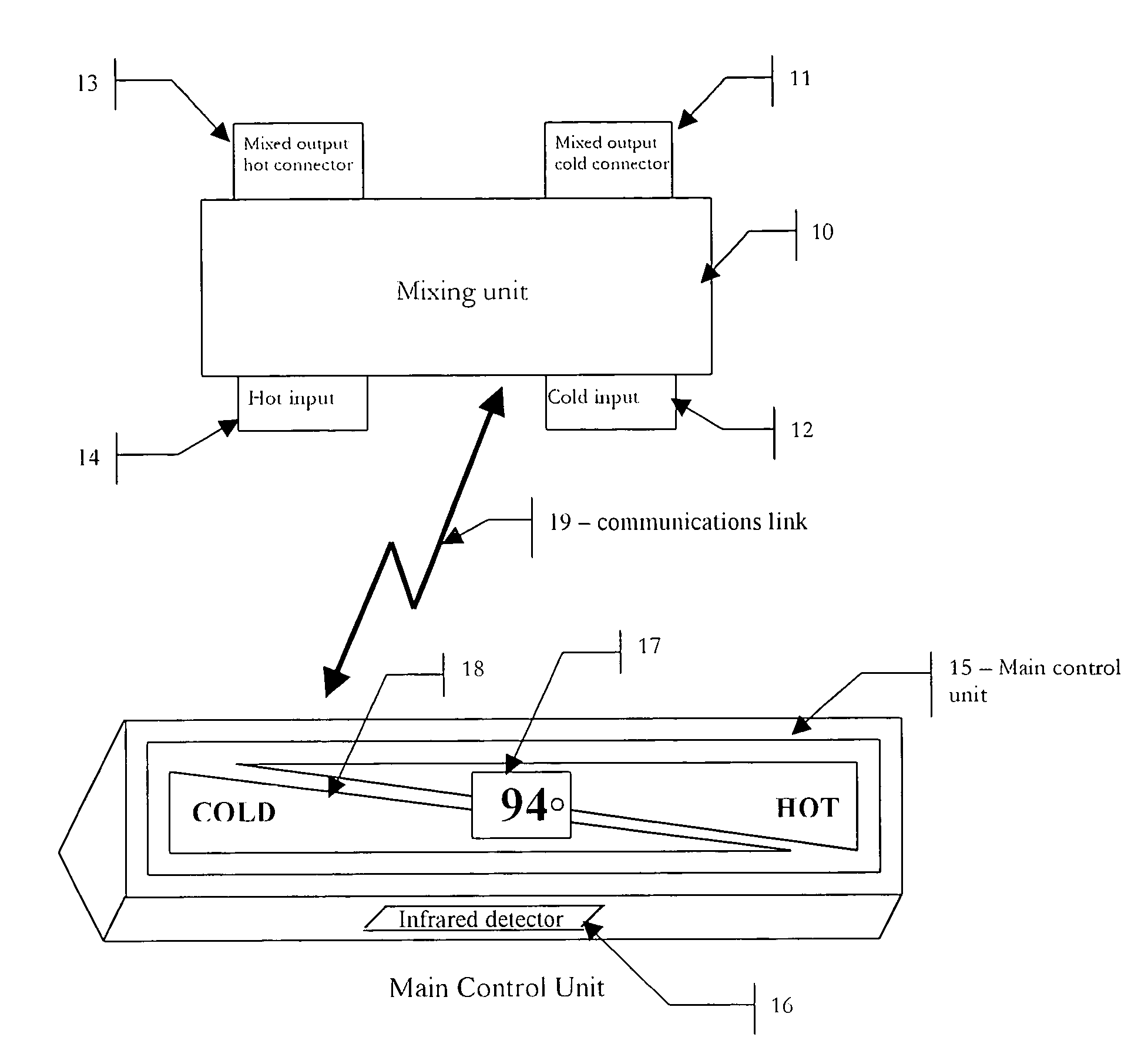
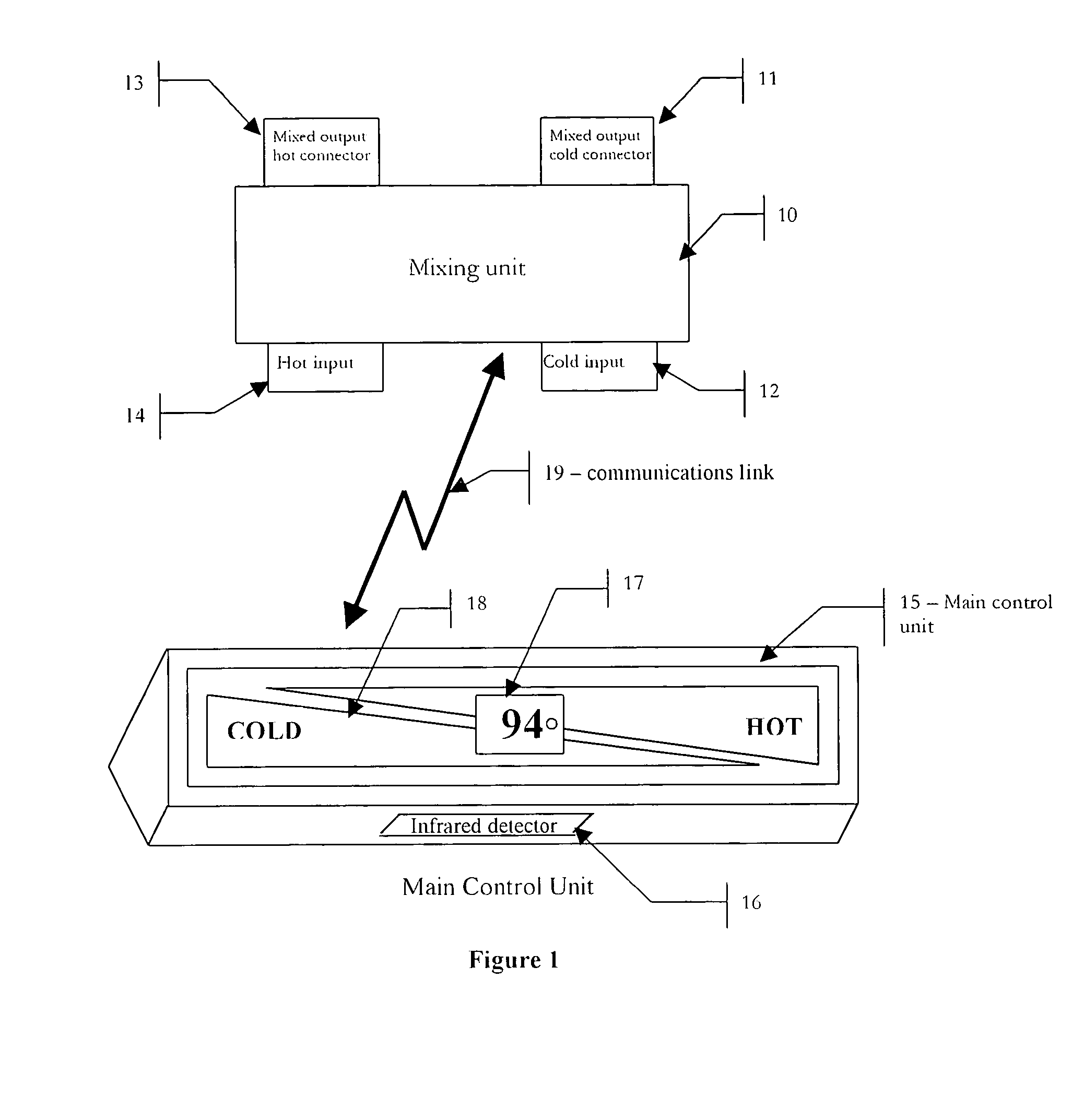
The present invention provides a means to add electronic control of temperature and flow rate for fluids in standard faucets. The device is self powered by means of the fluid flowing through it and generates sufficient power to operate the control electronics. Elimination of an external power source or internal battery, is important for simple retrofit installations as well as maintenance free operation for many years. The invention consists of two components that communicate with each other via either an RF (radio frequency), IR (infra red) or a wired link. The Mixing Unit serves to mix the incoming hot and cold fluids (typically water but any fluid can be mixed) to a desired temperature under control of the Main Control Unit. The Main Control Unit provides a means by which the user can adjust the temperature as well as automatically turn on and off the fluid flow.

Description

RELATED U.S. APPLICATIONS[0001]This first non-provisional patent applications makes claim to the Provisional Application for Patent filed Dec. 4, 2002 and titled Self powered electronically controlled mixing valve, of the same inventor ship and with the express mail label no ET848516824 US.Reference U.S. Patent Documents:[0002]U.S. Pat. No. 5,459,890 Water blending and recycling apparatus[0003]U.S. Pat. No. 5,570,869 Self calibrating water fluid control apparatus[0004]U.S. Pat. No. 5,611,517 Control unit for automatic faucet[0005]U.S. Pat. No. 5,915,417 Automatic fluid control valve apparatus[0006]U.S. Pat. No. 5,988,588 Control module for battery operated faucet[0007]U.S. Pat. No. 6,202,980 Electronic faucet B1[0008]U.S. Pat. No. 6,273,394 Electronic faucet[0009]U.S. Pat. No. 6,290,207 Electronic motorized zone valve[0010]U.S. Pat. No. 6,390,125 Valve system sanitary fixture[0011]U.S. Pat. No. 6,446,875 Water temperature and pressure control system[0012]U.S. Pat. No. 6,460,567 Seal...

Claims


Application Information

Patent Timeline
Patent Type & Authority Patents(United States)
IPC IPC(8): G05D23/13G05D23/01
CPCG05D23/1393Y10T137/86389Y10T137/9464
Inventor DELANGIS, ERIC
Owner DELANGIS ERIC
Why Eureka
Try Eureka