Locating assembly having an extendable clamping finger

a technology of locating assembly and clamping finger, which is applied in the field of locating pins, can solve the problems of high cost, difficult maintenance, and easy failure of the locating assembly disclosed in the '855 patent, and achieve the effects of faster work, more efficient manufacturing operations, and improved service li

Inactive Publication Date: 2005-07-05
WELKER BEARING
View PDF25 Cites 34 Cited by
  • Summary
  • Abstract
  • Description
  • Claims
  • Application Information

AI Technical Summary

Benefits of technology

[0011]The locating assembly, through the mechanism, precisely controls the finger so that the locating assembly works faster, more efficiently, more precisely, and more uniformly by extending and retracting the finger through the locating pin simultaneous with the rectilinear movement of the locating pin. Furthermore, the locating assembly does not require extensive maintenance, thus making manufacturing operations more efficient. The locating assembly is also self compensating to provide an ideal clamping force on work pieces of various size. Thus, when multiple locating assemblies are used, each assembly is self compensating to provide a uniform clamping force on the work piece.

Problems solved by technology

The locating assembly disclosed in the '855 patent, among other similar locating assemblies of the prior art, is expensive and difficult to maintain.
For instance, the hook disclosed in the '855 patent, while being subjected to forces in many directions, is prone to failure due to fatigue.
Furthermore, the hooks are limited to a single path of motion, depending on a shape of the first and second slots, and thus cannot be adjusted.
This may result in too great of a clamping force being applied to the work piece, causing denting, or conversely, too little clamping force, allowing the work piece to move while being worked on.
When using multiple clamping devices, clamping forces at each device may vary, resulting in clamping that is not uniform, damage to the work piece, or movement of the work piece while being worked on.
The extra time cuts down on production speeds and reduces efficiency.

Method used


Image

  • Locating assembly having an extendable clamping finger
  • Locating assembly having an extendable clamping finger
  • Locating assembly having an extendable clamping finger

Examples


Embodiment Construction

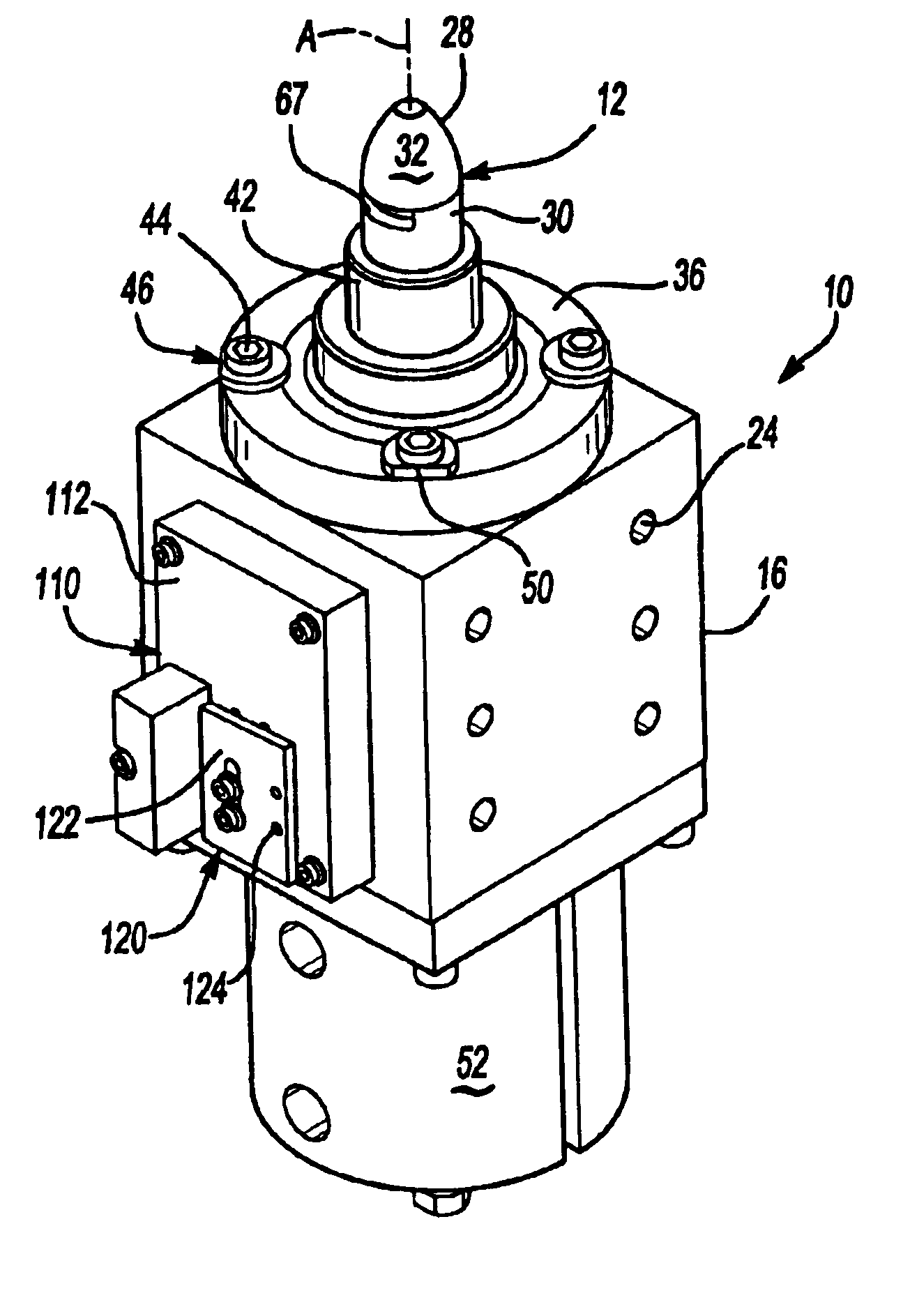
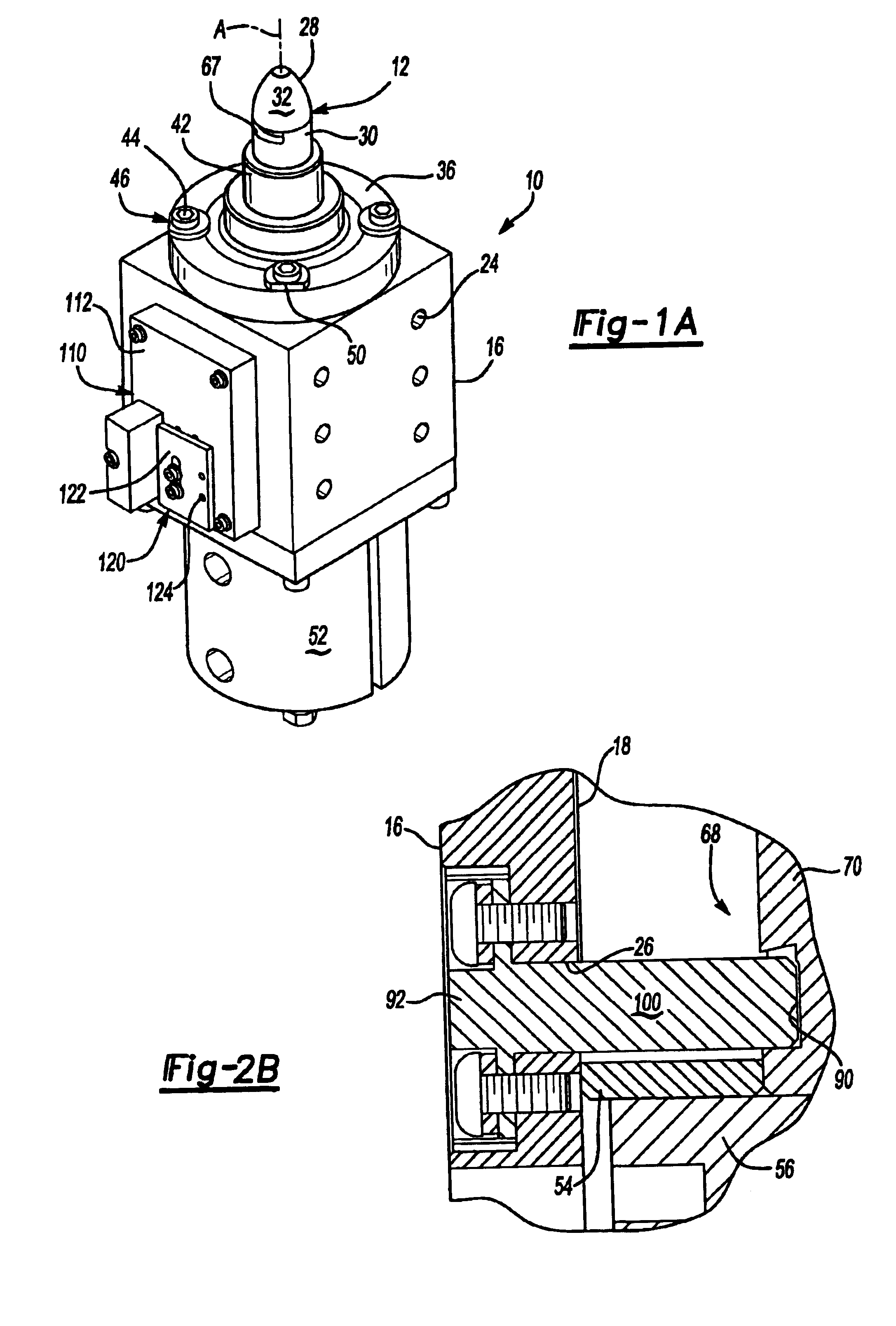
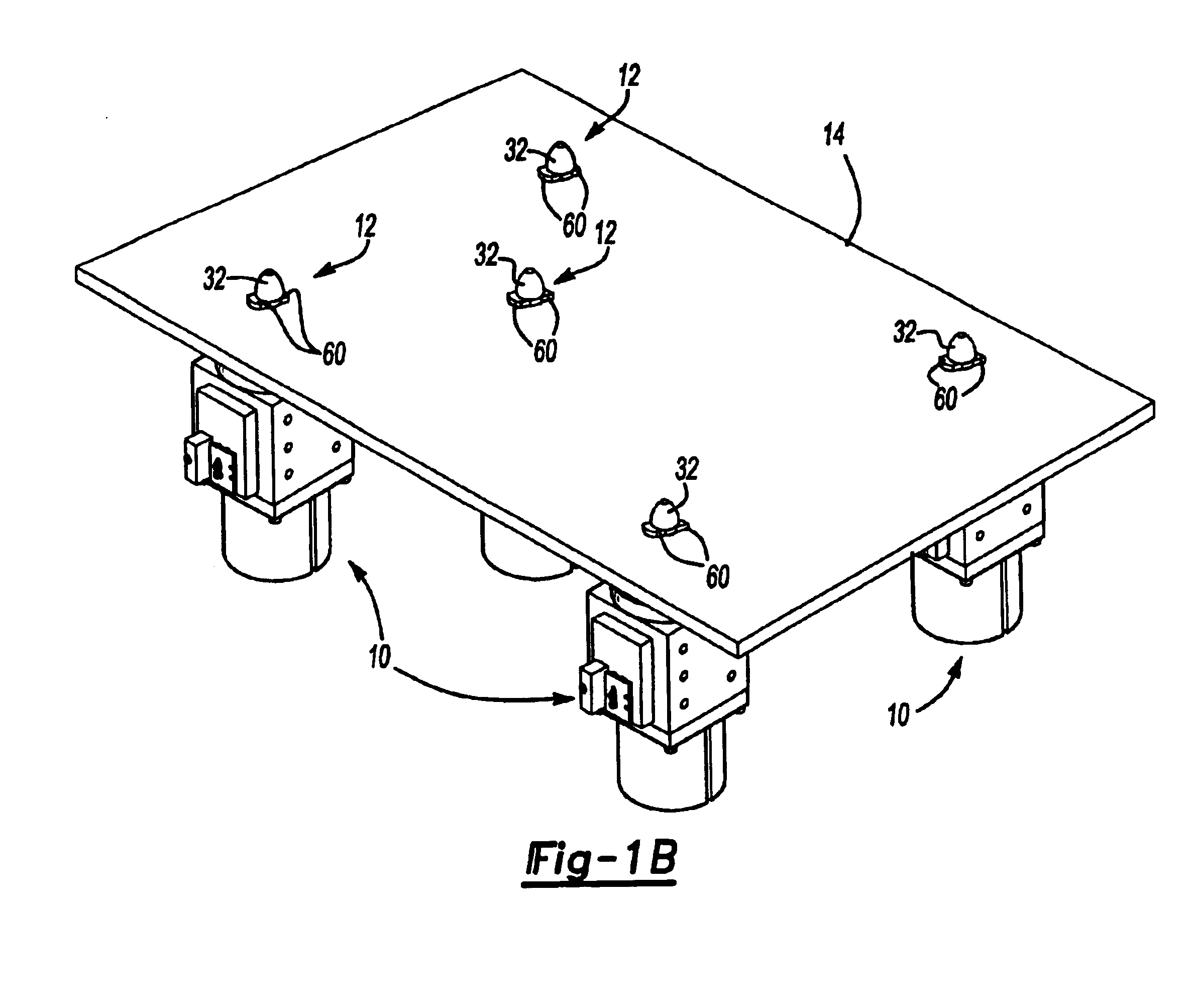
[0030]Referring to the Figures, wherein like numerals indicate like or corresponding parts throughout the several views, a locating assembly is generally shown at 10 in FIG. 1A. The locating assembly 10 includes a locating pin 12 that, as shown in FIG. 1B, positions and holds a work piece 14 so that work can be performed on the work piece 14. For example, the work piece 14 may be traveling on an assembly line to various stations, where work is performed on the work piece 14. The locating pin 12 precisely positions and holds the work piece 14 so that a person or machine performing the work may do so without the work piece 14 moving out of place. Preferably, the locating assembly 10 is located at the station. Upon arrival at the station, the work piece 14, which preferably defines a locating hole for receiving the locating pin 12, is placed on the locating assembly 10. The locating assembly 10 holds the work piece 14 with the locating pin 12 through the locating hole. Alternatively, t...


PUM


Abstract

The subject invention provides a locating assembly for centering and securing a work piece. The locating assembly includes a body. The body defines an internal cavity and an opening from the cavity to the exterior of the body. A locating pin is disposed in the cavity and extends along an axis out of the opening. An actuator moves the locating pin rectilinearly along the axis. A pair of fingers are supported by the locating pin and move radially into and out of the locating pin, transversely to the axis. A central post rotates in response to the rectilinear movement of the locating pin. A dowel extends from an end of the central post into a slot in the finger. The central post moves the dowel in an arcuate path through the slot to radially move the finger simultaneous with the rectilinear movement of the locating pin.

Description

RELATED APPLICATIONS[0001]This application is a continuation of U.S. Non-Provisional patent application Ser. No. 10 / 616,360, which was filed on Jul. 9, 2003 now U.S. Pat. No. 6,786,478, which claims priority to and all advantages of U.S. Provisional Patent Application No. 60 / 394,841, which was filed on Jul. 10, 2002.BACKGROUND OF THE INVENTION[0002]1. Field of the Invention[0003]The subject invention generally relates to locating pins for inserting into a work piece to position and hold the work piece. More specifically, the subject invention relates to a locating pin having an extendable finger or fingers for holding the work piece in place and for retracting into the locating pin to allow the work piece to be removed from the locating pin.[0004]2. Description of the Prior Art[0005]Various locating assemblies are known to those skilled in the art which employ a locating pin to precisely position a work piece. These locating assemblies include an extendable clamping arm, or finger, ...

Claims


Application Information

Patent Timeline
Patent Type & Authority Patents(United States)
IPC IPC(8): B23Q3/08B23Q1/00B27F1/00B23Q3/06B23Q3/18B23Q16/00B25B5/06B25B5/08
CPCB23Q3/18B23Q16/001B25B5/062B25B5/087B25B5/061
Inventor PAVLIK, JOSEPH M.HOLT, DOUGLAS J.ADAMS, JR., ROBERT C.
Owner WELKER BEARING
Why Eureka
Try Eureka