Suction valve coupling structure for reciprocating compressor

a compressor and suction valve technology, applied in the direction of liquid fuel engines, positive displacement liquid engines, piston pumps, etc., can solve the problem of lowering the reliability of the compressor

Inactive Publication Date: 2005-07-05
LG ELECTRONICS INC
View PDF17 Cites 15 Cited by
  • Summary
  • Abstract
  • Description
  • Claims
  • Application Information

AI Technical Summary

Benefits of technology

[0016]Therefore, an object of the present invention is to provide a suction valve coupling structure for a reciprocating compressor, in which the suction valve for opening and closing a gas flow passage is firmly coupled and the coupling structure is simplified, thereby minimizing dead volume.

Problems solved by technology

According to this, the suction valve deviates from the refrigerant suction hole 6e, thereby lowering a reliability of the compressor.

Method used


Image

  • Suction valve coupling structure for reciprocating compressor
  • Suction valve coupling structure for reciprocating compressor
  • Suction valve coupling structure for reciprocating compressor

Examples


Embodiment Construction

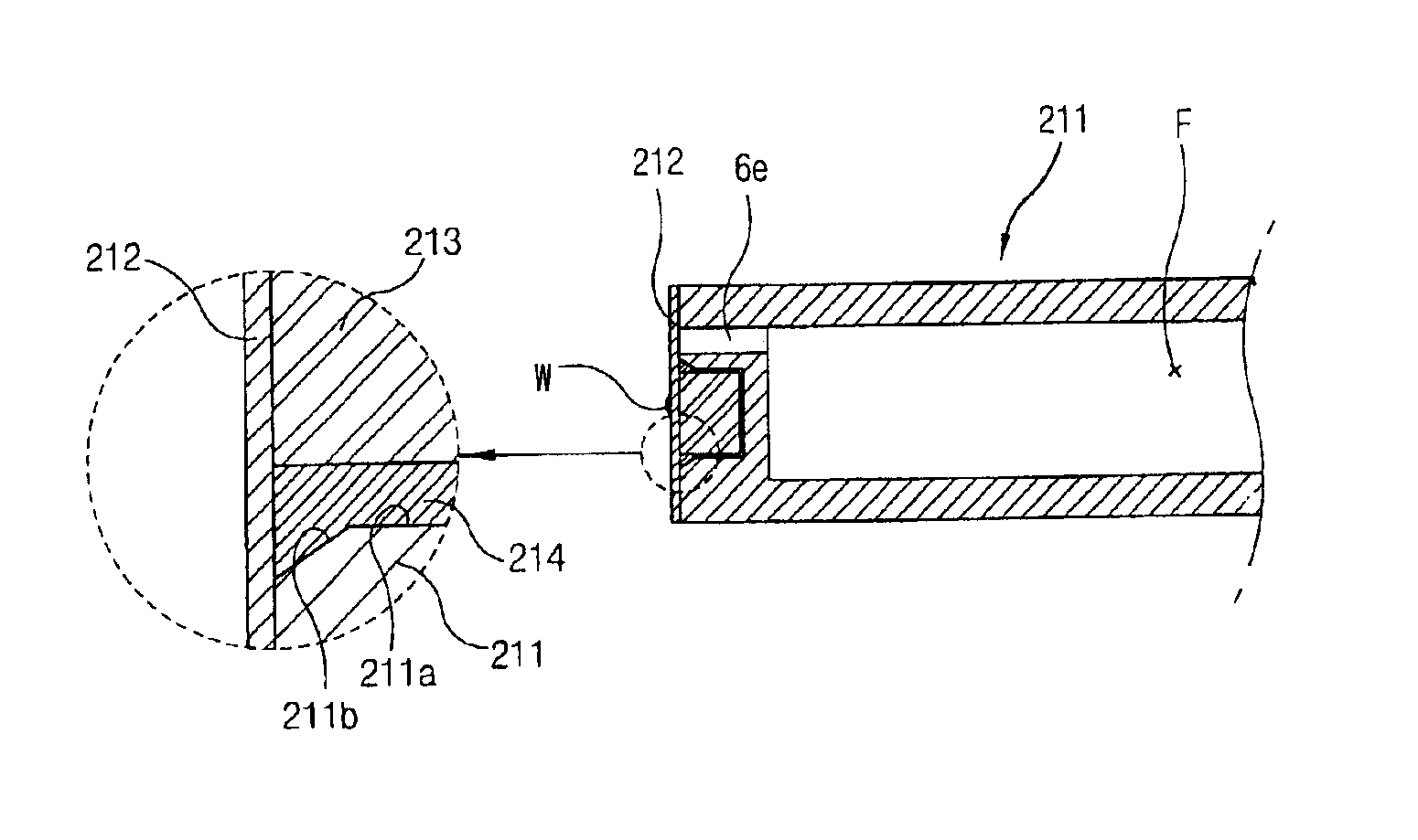
[0017]In order to achieve the above objects, there is provided a suction valve coupling structure for a reciprocating compressor, the reciprocating compressor comprising: a piston for linearly reciprocating in a cylinder with an armature of a reciprocating motor and having a refrigerant flow passage connected to the end portion surface thereof; and a suction valve arranged at the end portion surface of the piston for opening and closing the refrigerant flow passage, wherein a welding member mounting recess of a predetermined depth for mounting the suction valve is formed at the end portion surface of the piston.

[0018]Also, in order to achieve the above objects, there is provided a suction valve coupling structure for a reciprocating compressor, in which the suction valve is coupled to the piston by welding a lateral side surface thereof to a corresponding surface of the piston.

BRIEF DESCRIPTION OF THE DRAWINGS

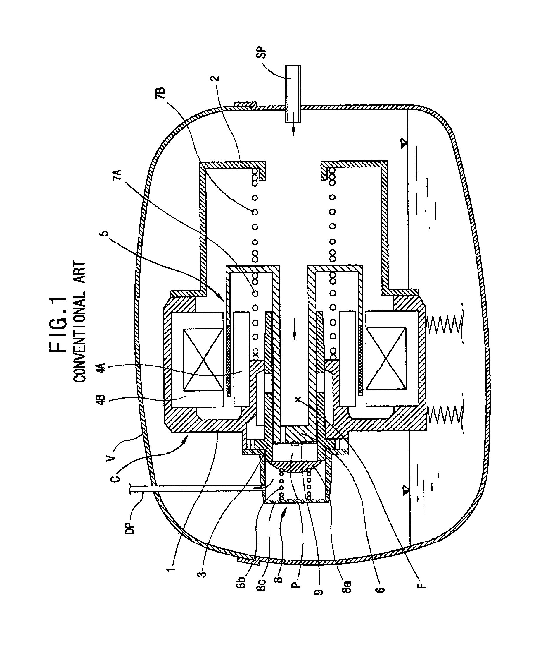
[0019]FIG. 1 is a longitudinal section view showing one embodiment of the ...


PUM


Abstract

A suction valve coupling structure for a reciprocating compressor is disclosed in which a piston being linearly moved in a cylinder upon receipt of driving force from an electric mechanism unit, according to which gas flows through a gas flow passage formed therein, is coupled by welding to a valve for opening and closing the gas flow passage, thereby strengthening the coupling state of the suction valve. Since the coupling structure is simplified, a dead volume is reduced and a stroke volume is increased, improving compression efficiency. A stroke control of the piston is facilitated to enable a precise control of movement of the piston. In addition, a reliability of the coupling of the suction valve can be improved.

Description

TECHNICAL FIELD[0001]The present invention relates to a reciprocating compressor, and particularly to a suction valve coupling structure for a reciprocating compressor, in which the suction valve for opening and closing a gas flow passage is firmly coupled and the coupling structure is simplified, thereby minimizing a dead volume.BACKGROUND ART[0002]Conventionally, a compressor is a device for compressing a fluid such as air and refrigerant gas. The compressor includes a motor unit installed in the hermetic container for generating driving force, and a compression unit for sucking and compressing gas by receiving the driving force of the motor unit. In the compressor, if a power source is applied to generate the driving force in the motor unit, the driving force is transmitted to the compression unit, thereby sucking, compressing, and discharging gas in the compression unit.[0003]A reciprocating compressor is a device, in which a piston is coupled to an armature of a reciprocating m...

Claims


Application Information

Patent Timeline
Patent Type & Authority Patents(United States)
IPC IPC(8): F04B39/10F04B39/00F04B35/00F04B35/04F04B39/12F04B39/14
CPCF04B35/045F04B39/1073F04B39/0016Y10T137/784Y10T137/6086
Inventor HONG, SEONG-JOONKU, BON-CHEOLKIM, HYEONG-SUKYOON, HYUNG-PYO
Owner LG ELECTRONICS INC
Why Eureka
Try Eureka