

Material removal monitor
Inactive Publication Date: 2005-07-05
GRIVNA HOWARD W
View PDF16 Cites 8 Cited by
- Summary
- Abstract
- Description
- Claims
- Application Information
AI Technical Summary
Benefits of technology
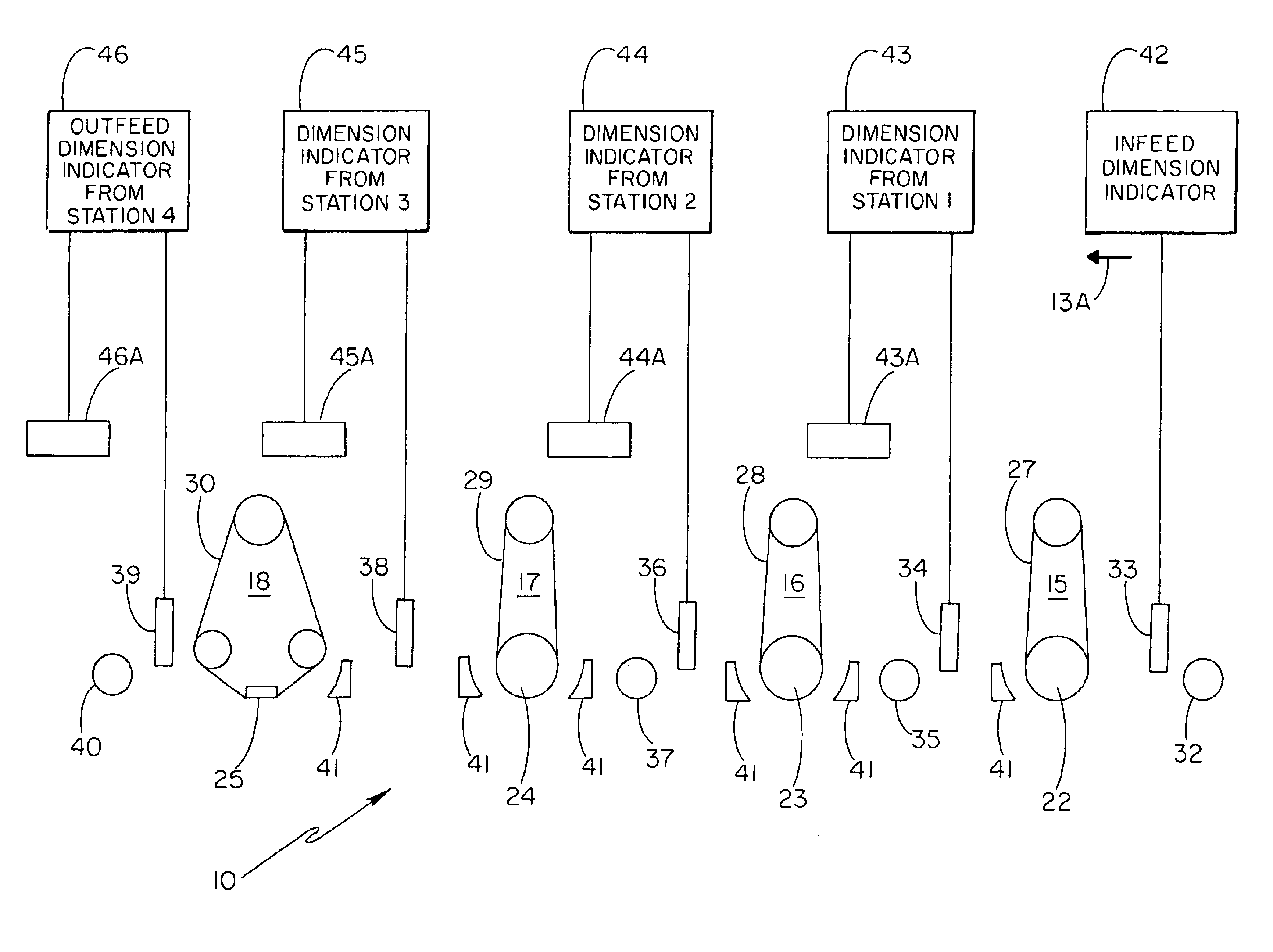
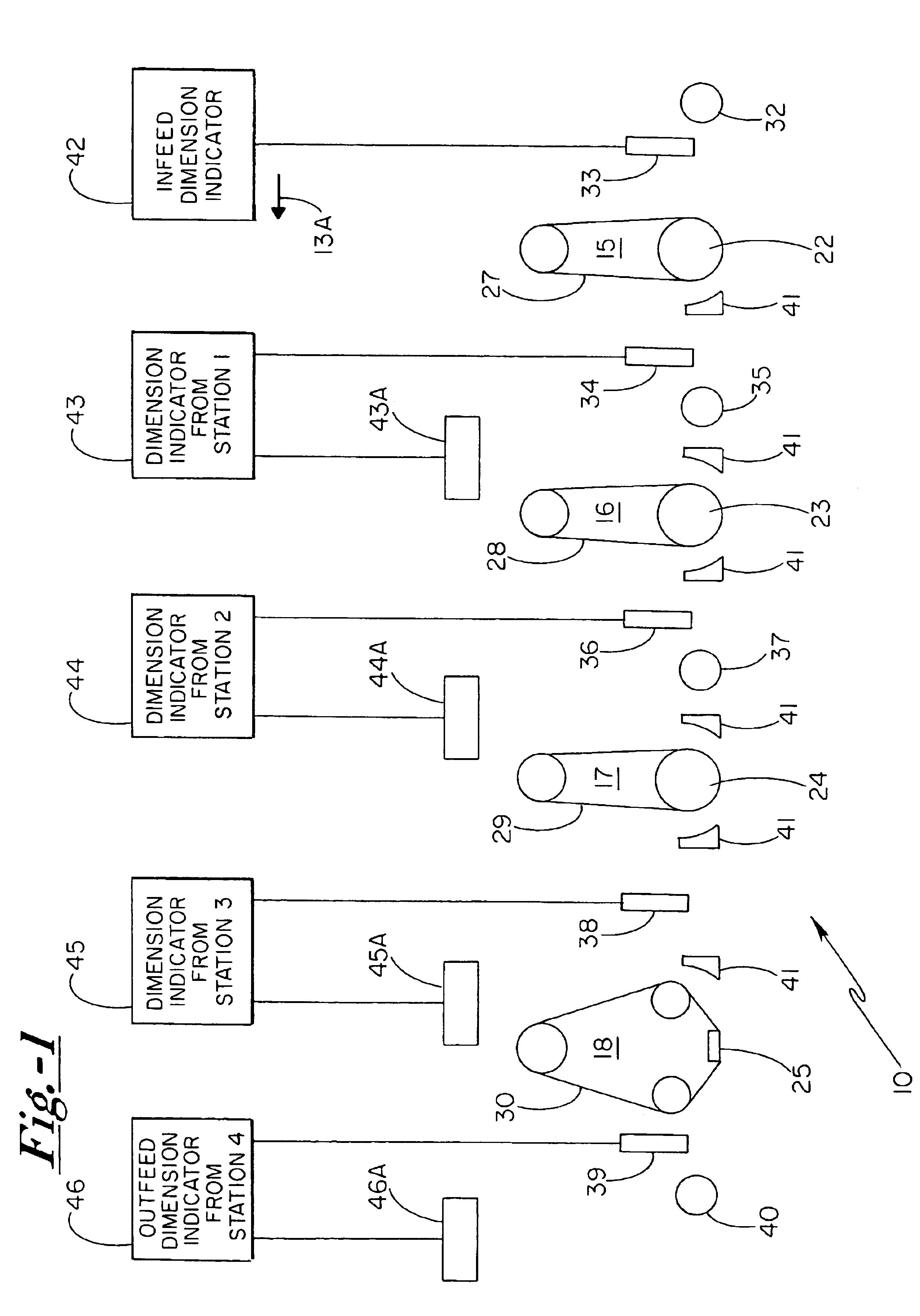
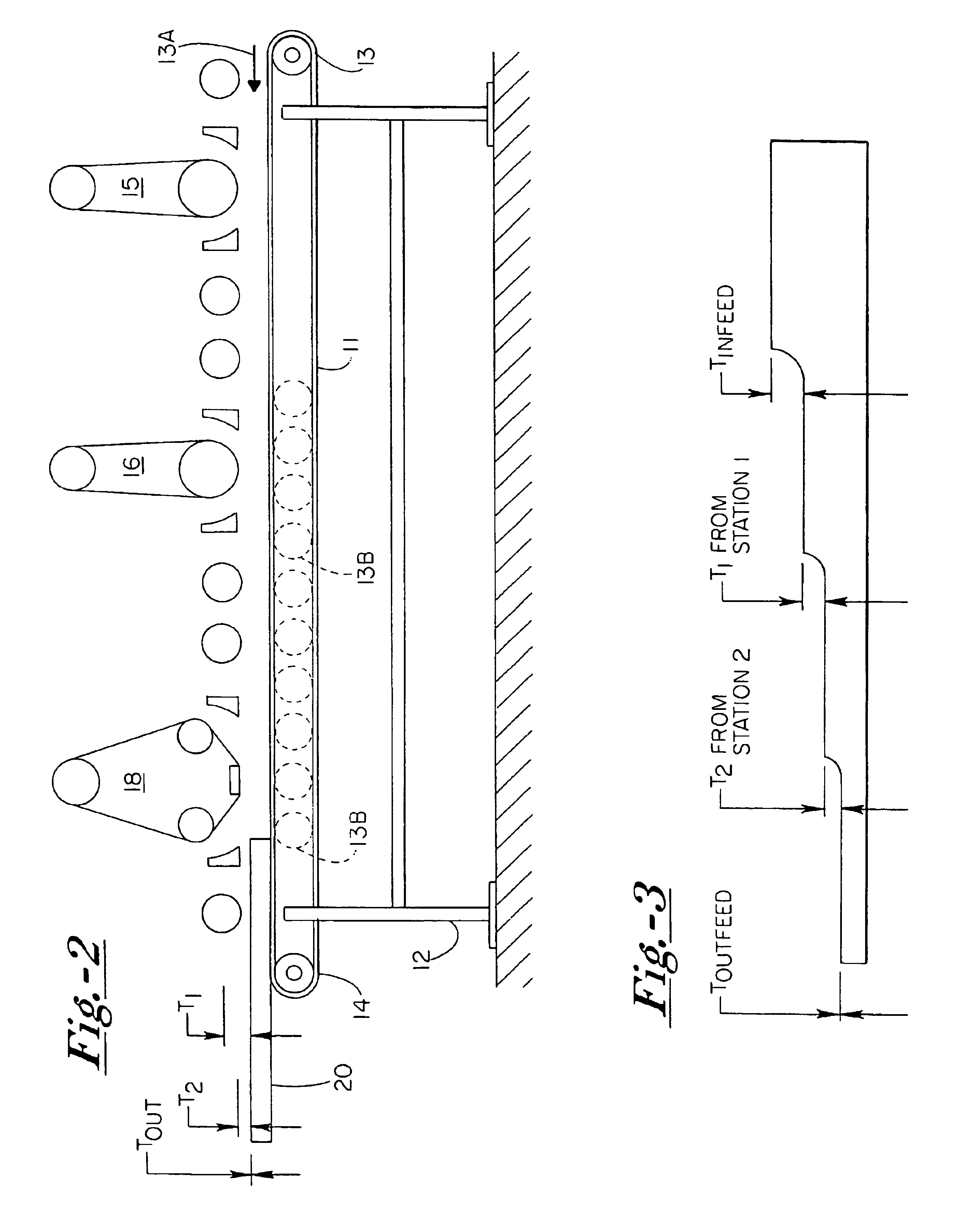
[0008]The infeed end of the system and along with each of the work stations is provided with a workpiece dimension indicator. The infeed dimension indicator is employed to reject or eliminate workpieces which are not within the nominal size range. The remaining dimension indicators are positioned to measure a deviation dimension from the datum plane as they leave an individual work station. The dimension indicators comprise dimension responsive detector means for generating a signal responsive to the deviation from datum plane being measured for each workpiece. Accordingly, the extent of stock removal achieved on each workpiece is readily determined. The information obtained from the dimension responsive detector means may be utilized by a system operator to adjustably position the working heads to maintain proper stock removal while machine operation continues.
[0012]Feed speed is a parameter affecting overall system operation. Slower conveyor feed speeds permit each belt to remove more material or stock from the workpiece and thereby minimize belt loading which may ultimately contribute to streaking. Inasmuch as abrasive belt speed is generally fixed, belt loading may be advantageously controlled through monitoring of feed speed.
Problems solved by technology
An additional cause of uneven belt wear and / or uneven sanding performance is in the tendency for wide-belt sanding heads to fall out of planar parallel relationship with the plane defined by the workpiece conveyor.
Such a situation results in uneven sanding of the workpiece, as well as uneven wear upon the sanding belt.
Method used
View moreImage
Smart ImageViewing Examples

Examples
example i
[0039 provides an indication of the parameters useful in stock removal for a fine finish on hard maple. The system operator may be provided with predetermined information indicative of the type of wood in the workpiece, as well as parameters including grit utilized at each station, belt speed, and conveyor speed.
Login to View More PUM
 Abstract
A material removal optimizing system for a wood surface treating apparatus with a plurality of individual work stations arranged serially along an endless conveyor. Each station includes a working abrasive head along with an elevation adjustment mechanism for adjustably positioning the contact surface of each abrasive head at a desired working distance from the opposed surface of the workpiece traveling along the endless conveyor. An incoming workpiece dimension indicator is positioned at the infeed end, and additional workpiece dimension indicators are positioned downstream from each work station, with each dimension indicator being positioned to measure the dimensional deviation of the workpiece from a datum plane after it has passed through its preceding individual work station.
Description
CROSS-REFERENCE TO RELATED APPLICATION[0001]The present application is a continuation-in-part of our application Ser. No. 10 / 225,330, filed Aug. 21, 2002 now U.S. Pat. No. 6,769,958, entitled “MATERIAL REMOVAL MONITOR”, the content of which is incorporated herein in its entirety.BACKGROUND OF THE INVENTION[0002]The present invention relates generally to an improved apparatus and system for monitoring and controlling the operation of individual work stations within a sanding system having a plurality of such stations functioning in combination with a continuous feed system such as an endless conveyor belt or roll feed. Other continuous feed systems, such as reciprocating systems or rotary feed systems are applicable. Such systems are in wide use today, and typically employ abrasive workpiece surfacing heads, such as drum heads and platen heads. These heads are arranged serially adjacent to and typically elevated from the surface of the conveyor, and treat the workpieces as they move ...
Claims
Login to View More Application Information
Patent Timeline
 IPC IPC(8): B24B21/04B24B27/00B24B19/24B24B19/00B24B7/06B24B51/00B24B7/00B24B5/00B24B21/00B24B21/12B24B49/00B24B49/04
CPCB24B7/06B24B7/28B24B19/24B24B21/04B24B21/12B24B27/0023B24B49/04B24B51/00
InventorGRIVNA, HOWARD W.
OwnerGRIVNA HOWARD W