
Mass spectrometer

a mass spectrometer and ion mobility technology, applied in the field of mass spectrometers, can solve the problems of ion guides that are relatively long, lose substantially all their forward motion, and scattering,

Inactive Publication Date: 2005-07-05
MICROMASS UK LTD
View PDF49 Cites 93 Cited by
  • Summary
  • Abstract
  • Description
  • Claims
  • Application Information

AI Technical Summary

Benefits of technology

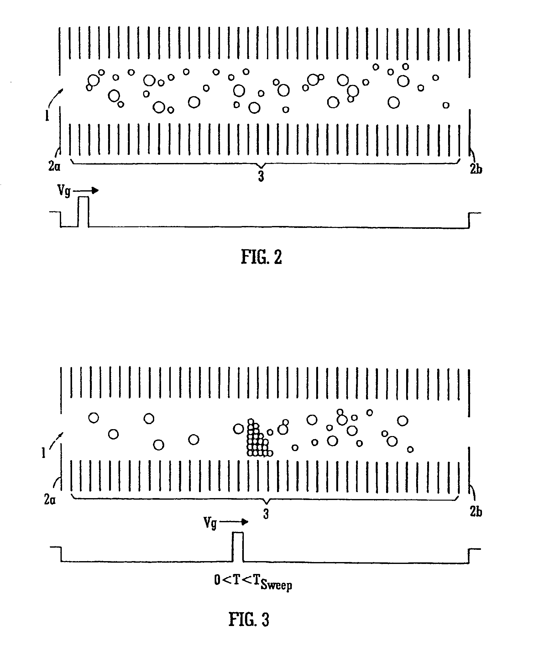
[0101]The ion mobility separator preferably comprises a plurality of electrodes and wherein one or more transient DC voltages or one or more transient DC voltage waveforms are progressively applied to the electrodes so as to urge at least some ions in a first direction and wherein a DC voltage gradient acts to urge at least some ions in a second direction, the second direction being opposed to the first direction.
[0102]The peak amplitude of the one or more transient DC voltages or the one or more transient DC voltage waveforms preferably remains substantially constant or reduces along the length of the ion mobility separator.

Problems solved by technology

However, although the collisions with gas molecules may cause the ions to scatter and lose energy, the pseudo-potential well generated by the RF ion guide acts to radially confine the ions within the ion guide.
In such arrangements ions are held in orbit around the central guide wire and if ions undergo many collisions with gas molecules then they will tend to lose energy and will eventually collapse into the central guide wire and hence be lost.
When ions collide with gas molecules they may get scattered and lose kinetic energy.
Accordingly, under some operating conditions, ions being transported through an RF ion guide maintained at an intermediate gas pressure can lose substantially all their forward motion and may remain within the ion guide for a relatively long period of time.
However, without these influences the ions can, in effect, come to a substantial standstill within the ion guide and hence not emerge at the exit.

Method used


Image

  • Mass spectrometer
  • Mass spectrometer
  • Mass spectrometer

Examples


Embodiment Construction

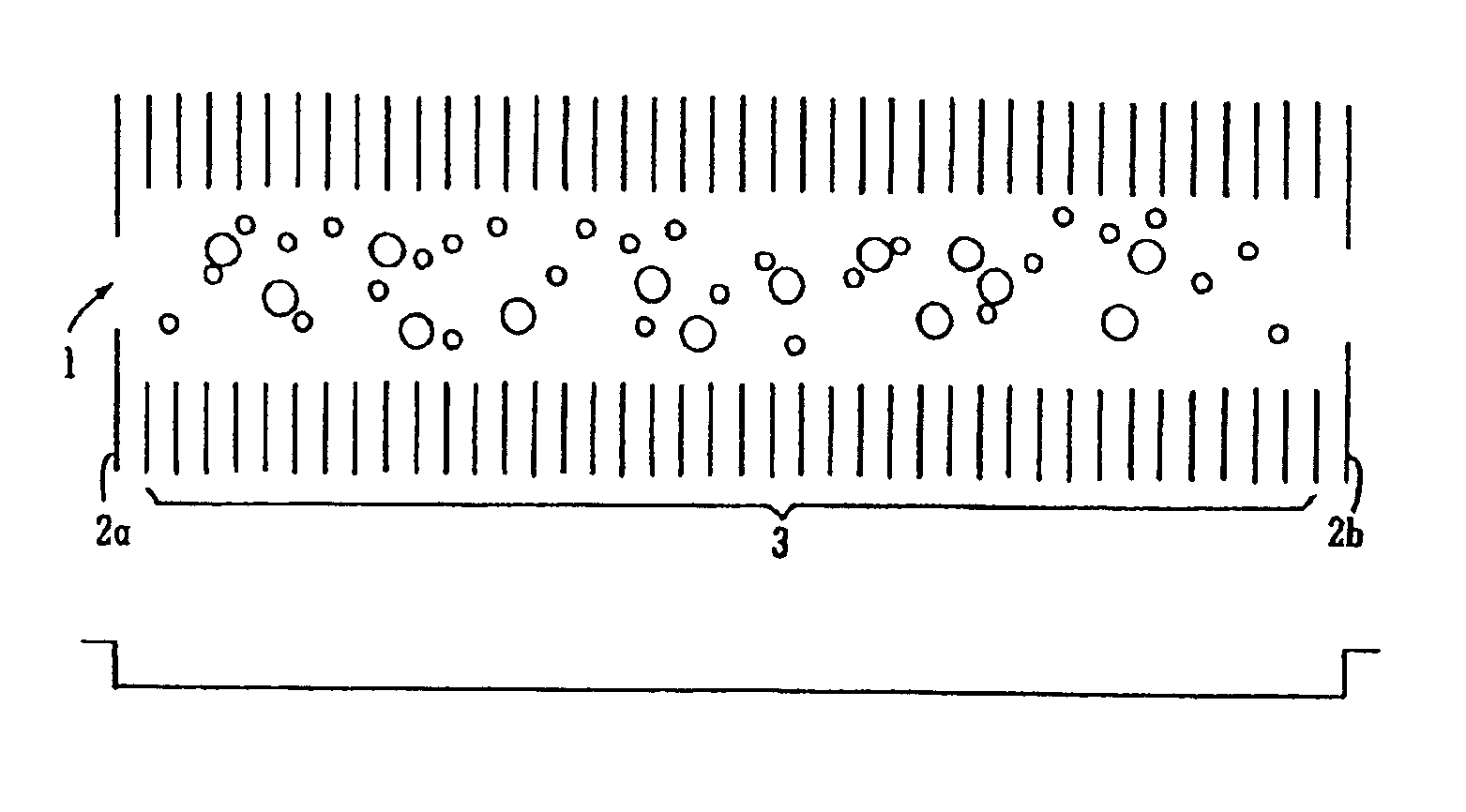
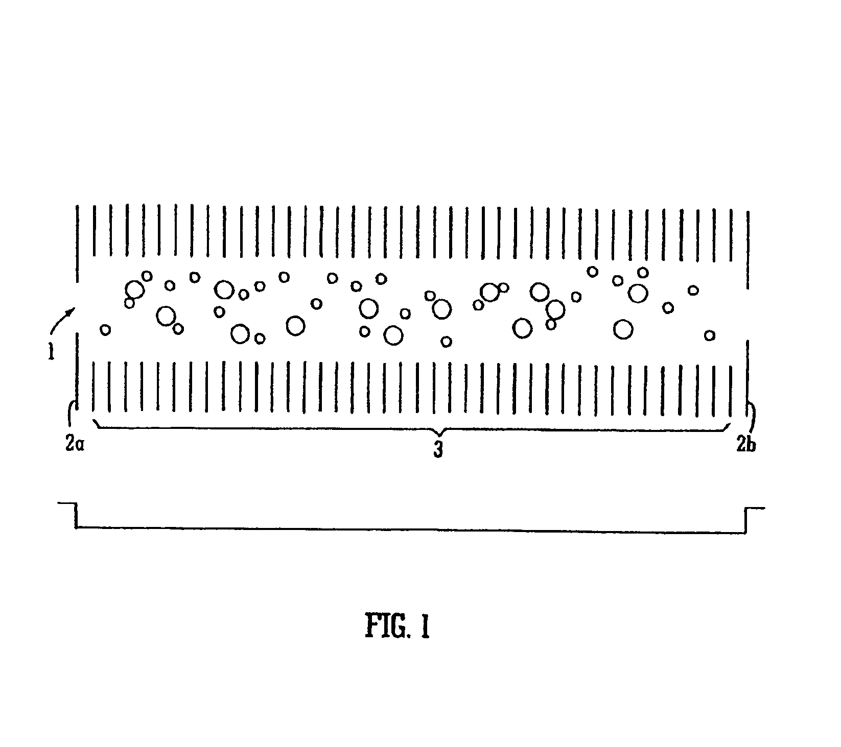
[0128]FIG. 1 shows a preferred ion mobility separator 1 comprising a plurality of electrodes 3 each having an aperture through which ions may be transmitted. Adjacent electrodes 3 are preferably connected to opposite phases of an AC or RF voltage supply. The ion mobility separator 1 is preferably held at a pressure such that ions traversing its length undergo many collisions with gas molecules. The ion mobility separator 1 may according to one embodiment receive ions generated by an Electrospray or a MALDI ion source. One or more end plates 2a,2b of the ion mobility separator 1 may be maintained at a slight positive voltage relative to the other electrodes 3 so that ions once entering the ion mobility separator 1 are effectively trapped within the ion mobility separator 1 and are unable to surmount the potential barrier at one or both ends. After a certain period of time equilibrium may be reached within the ion mobility separator 1 so that ions of all masses and mobilities are subs...


PUM


Abstract

A mass spectrometer comprising an ion mobility separator for separating ions according to their ion mobility is disclosed. The ion mobility separator comprises a plurality of electrodes and one or more transient DC voltages or one or more transient DC voltage waveforms are progressively applied to the electrodes so that ions having a certain ion mobility are separated from other ions having different ion mobilities.

Description

CROSS-REFERENCE TO RELATED APPLICATIONS[0001]The present application represents a continuation of U.S. patent application Ser. No. 10 / 603,824 filed Jun. 26, 2003 now U.S. Pat. No. 6,791,078 which claims the benefit of the filing date of U.S. Provisional Patent Application Ser. No. 60 / 422,134 filed Oct. 30, 2002.BACKGROUND OF THE INVENTION[0002]1. Field of the Invention[0003]The present invention relates to a mass spectrometer, an ion mobility separator, a method of mass spectrometry and a method of ion mobility separation.[0004]2. Discussion of the Prior Art[0005]Radio Frequency (RF) ion guides are commonly used for confining and transporting ions. Conventionally a plurality of electrodes are provided wherein an RF voltage is applied between neighbouring electrodes so that a pseudo-potential well or valley is produced. The pseudo-potential well can be arranged to radially confine ions and may be used to efficiently transport ions by acting as an ion guide.[0006]The RF ion guide is c...

Claims


Application Information

Patent Timeline
Patent Type & Authority Patents(United States)
IPC IPC(8): H01J49/34H01J49/00H01J49/40
CPCG01N27/622G01N27/623
Inventor GILES, KEVINHOYES, JOHN BRIANPRINGLE, STEVEWILDGOOSE, JASON LEE
Owner MICROMASS UK LTD
Learn More