
Adaptive keeper sizing for dynamic circuits based on fused process corner data

a dynamic circuit and keeper transistor technology, applied in logic circuits, pulse techniques, electrical apparatus, etc., can solve the problems of adversely affecting evaluation performance, keeper transistor b>116/b> cannot be made arbitrarily large, evaluation transistors b> cannot be made large, etc., and achieve the effect of increasing flexibility

Inactive Publication Date: 2005-07-05
ORACLE INT CORP
View PDF5 Cites 24 Cited by
  • Summary
  • Abstract
  • Description
  • Claims
  • Application Information

AI Technical Summary

Benefits of technology

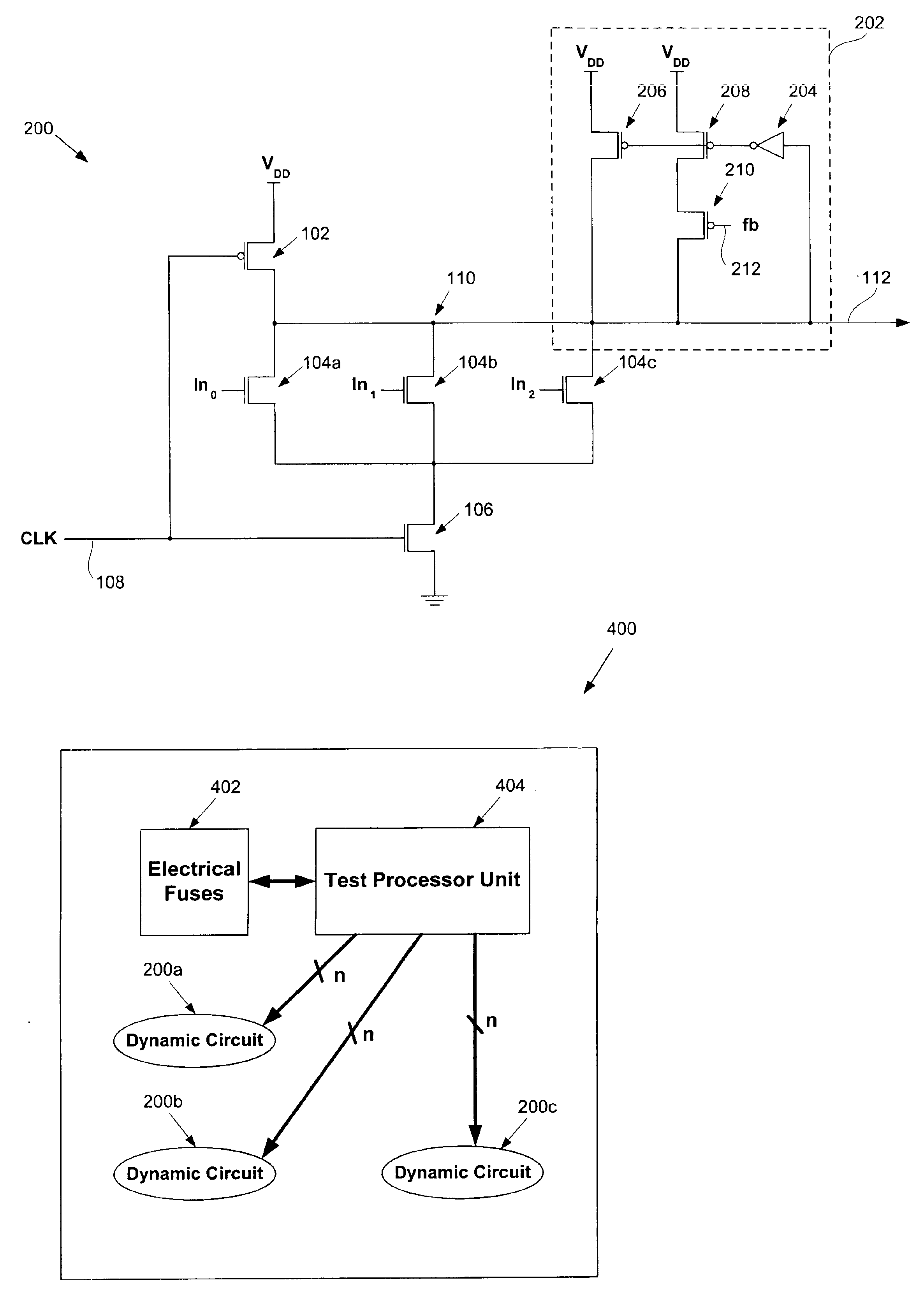
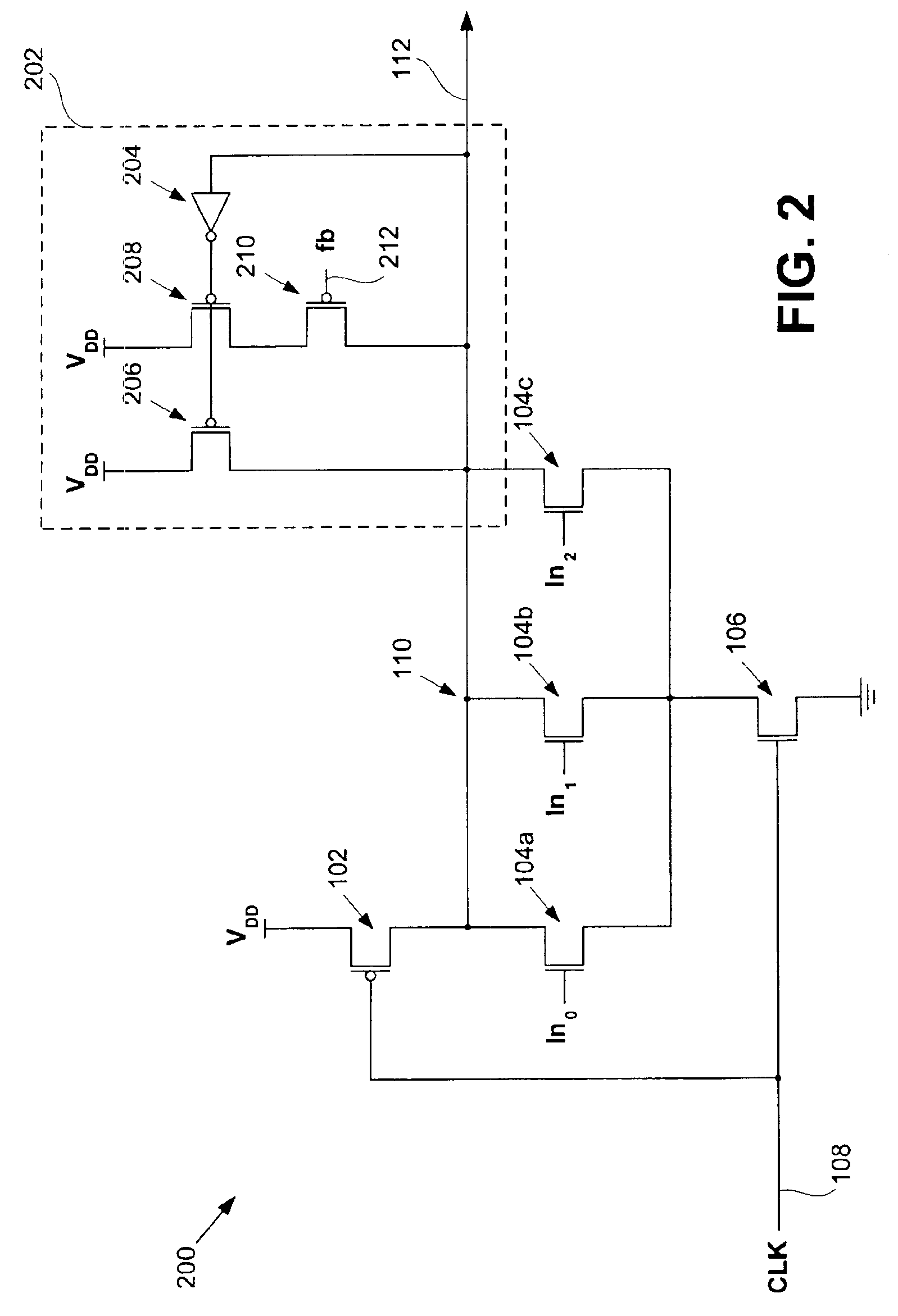
[0016]Broadly speaking, the present invention fills these needs by providing adaptive keeper transistor sizing in dynamic circuits based on fused process corner data. In one embodiment, an adaptive keeper circuit is disclosed. The adaptive keeper circuit includes a first keeper transistor having a first terminal in electrical communication with a power supply and a second terminal in electrical communication with an internal dynamic node. In addition, a second keeper transistor is included that is configured in parallel to the first keeper transistor. The second keeper transistor also has a first terminal in electrical communication with the power supply. The second keeper transistor can be added to the first keeper transistor using a feedback bit line, which is configured to control current flow between the second keeper transistor and the internal dynamic node based on a state of the feedback bit line. The state of the feedback bit line is based on a process corner characteristic of the die. Additional keeper transistors and corresponding feedback bit lines can be added to the keeper circuit to increase flexibility.

Problems solved by technology

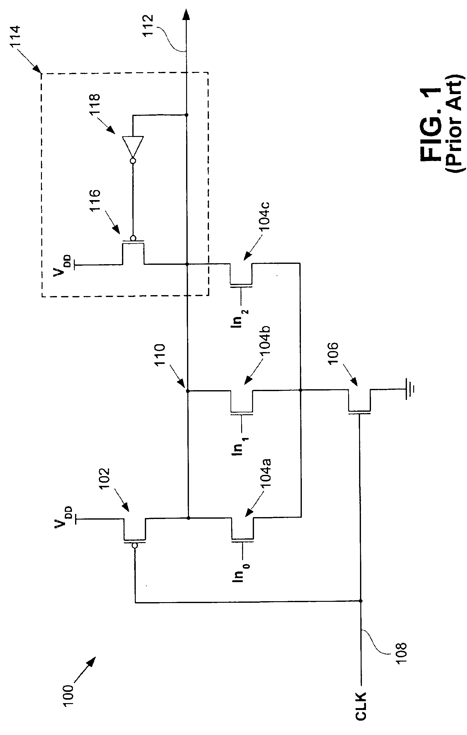
Unfortunately, the evaluation transistors 104a-104c leak.
It should be noted that the keeper transistor 116 cannot be made arbitrarily large because the keeper transistor circuit 114 will adversely affect evaluation performance if the keeper transistor 116 is too large.
Unfortunately, this also imposes a limit on the number of evaluation devices that can be included in a conventional dynamic circuit.

Method used


Image

  • Adaptive keeper sizing for dynamic circuits based on fused process corner data
  • Adaptive keeper sizing for dynamic circuits based on fused process corner data
  • Adaptive keeper sizing for dynamic circuits based on fused process corner data

Examples


Embodiment Construction

[0025]An invention is disclosed for adaptive keeper transistor sizing in dynamic circuits based on fused process corner data. Broadly speaking, embodiments of the present invention adjust the effective keeper transistor size by enabling additional keeper transistors based on the characteristics of the particular dynamic circuit (i.e., Process corner). As described in greater detail below, these characteristics are determined by examining data electrically programmed onto the die. In the following description, numerous specific details are set forth in order to provide a thorough understanding of the present invention. It will be apparent, however, to one skilled in the art that the present invention may be practiced without some or all of these specific details. In other instances, well known process steps have not been described in detail in order not to unnecessarily obscure the present invention.

[0026]As mentioned above, embodiments of the present invention adjust the effective s...


PUM


Abstract

An invention is provided for an adaptive keeper circuit. The adaptive keeper circuit includes a first keeper transistor having a first terminal in electrical communication with a power supply and a second terminal in electrical communication with an internal dynamic node. In addition, a second keeper transistor is included that is configured in parallel to the first keeper transistor. The second keeper transistor also has a first terminal in electrical communication with the power supply. The second keeper transistor can be added to the first keeper transistor using a feedback bit line, which is configured to control current flow between the second keeper transistor and the internal dynamic node based on a state of the feedback bit line. The state of the feedback bit line is based on a process corner characteristic of the die. Additional keeper transistors and corresponding feedback bit lines can be added to the keeper circuit to increase flexibility.

Description

CROSS REFERENCE TO RELATED APPLICATIONS[0001]This application is related to U.S. patent application Ser. No. 10 / 246,336, filed Sep. 17, 2002, and entitled “Process Monitor Based Keeper Scheme For Dynamic Circuits,” which is incorporated herein by reference.BACKGROUND OF THE INVENTION[0002]1. Field of the Invention[0003]This invention relates generally to keeper circuits, and more particularly to adaptive keeper transistor sizing for dynamic circuits based on global process corner data.[0004]2. Description of the Related Art[0005]Conventionally, keeper circuits have been utilized in dynamic circuits to prevent leaking at an internal dynamic node. For example, dynamic wide OR circuits commonly utilized in large register files often use keeper circuits to prevent unintentional discharging of the internal dynamic node, as illustrated in FIG. 1.[0006]FIG. 1 is a schematic diagram showing a conventional dynamic wide OR circuit 100. The dynamic wide OR circuit 100 includes a precharge p-ch...

Claims


Application Information

Patent Timeline
IPC IPC(8): H03K19/096
CPCH03K19/0963
Inventor GAUTHIER, CLAUDE R.DESAI, SHAISHAV A.
Owner ORACLE INT CORP
Learn More