
Deflection yoke and CRT device

a technology of deflection yoke and cathode ray tube, which is applied in the direction of electric discharge tube, magnetic body, instruments, etc., can solve problems such as energy-saving techniques, and achieve the effects of effective energy-saving, and reducing electric power consumption

Inactive Publication Date: 2005-07-05
PANASONIC CORP
View PDF7 Cites 7 Cited by
  • Summary
  • Abstract
  • Description
  • Claims
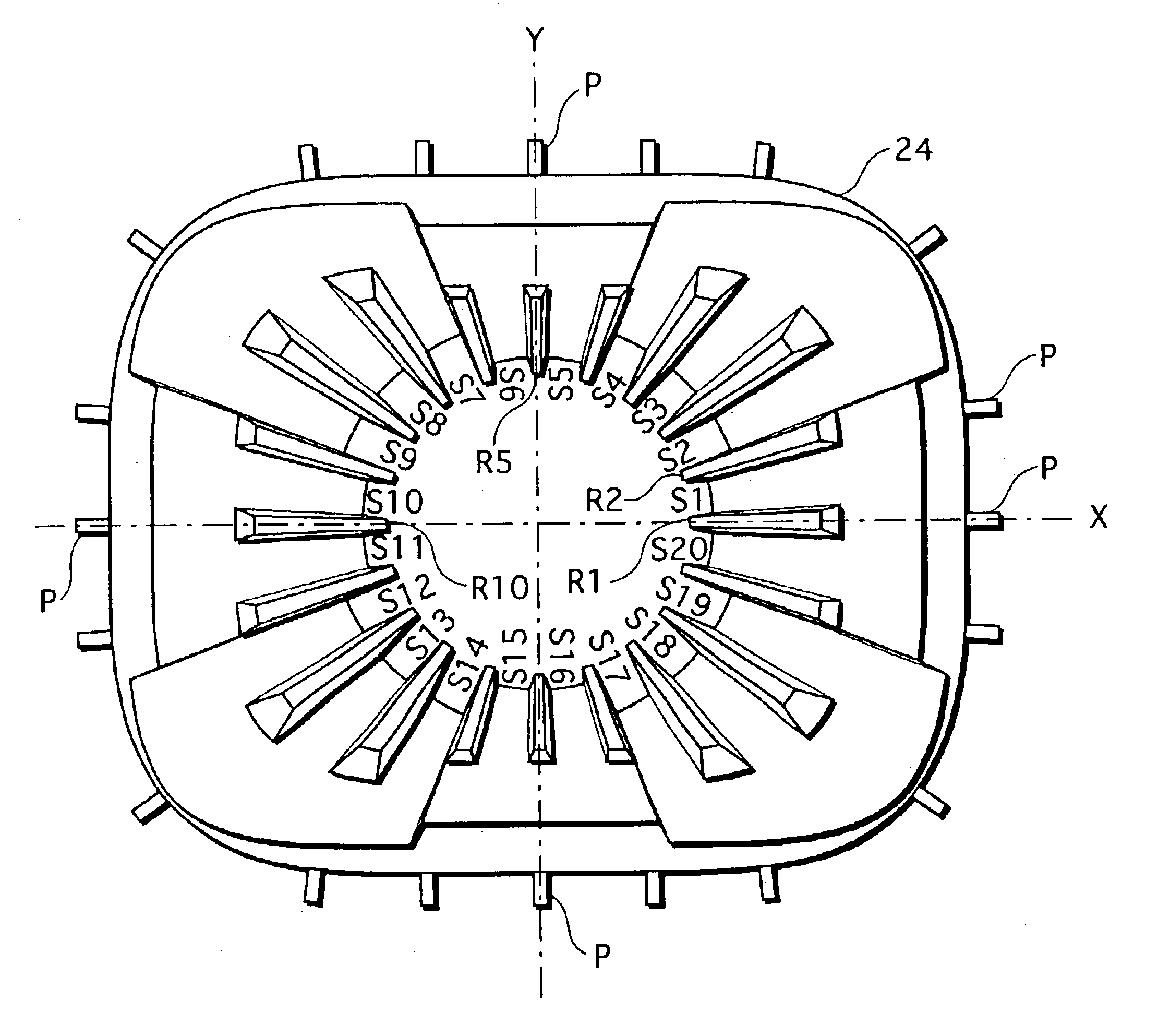
  • Application Information

AI Technical Summary

Benefits of technology

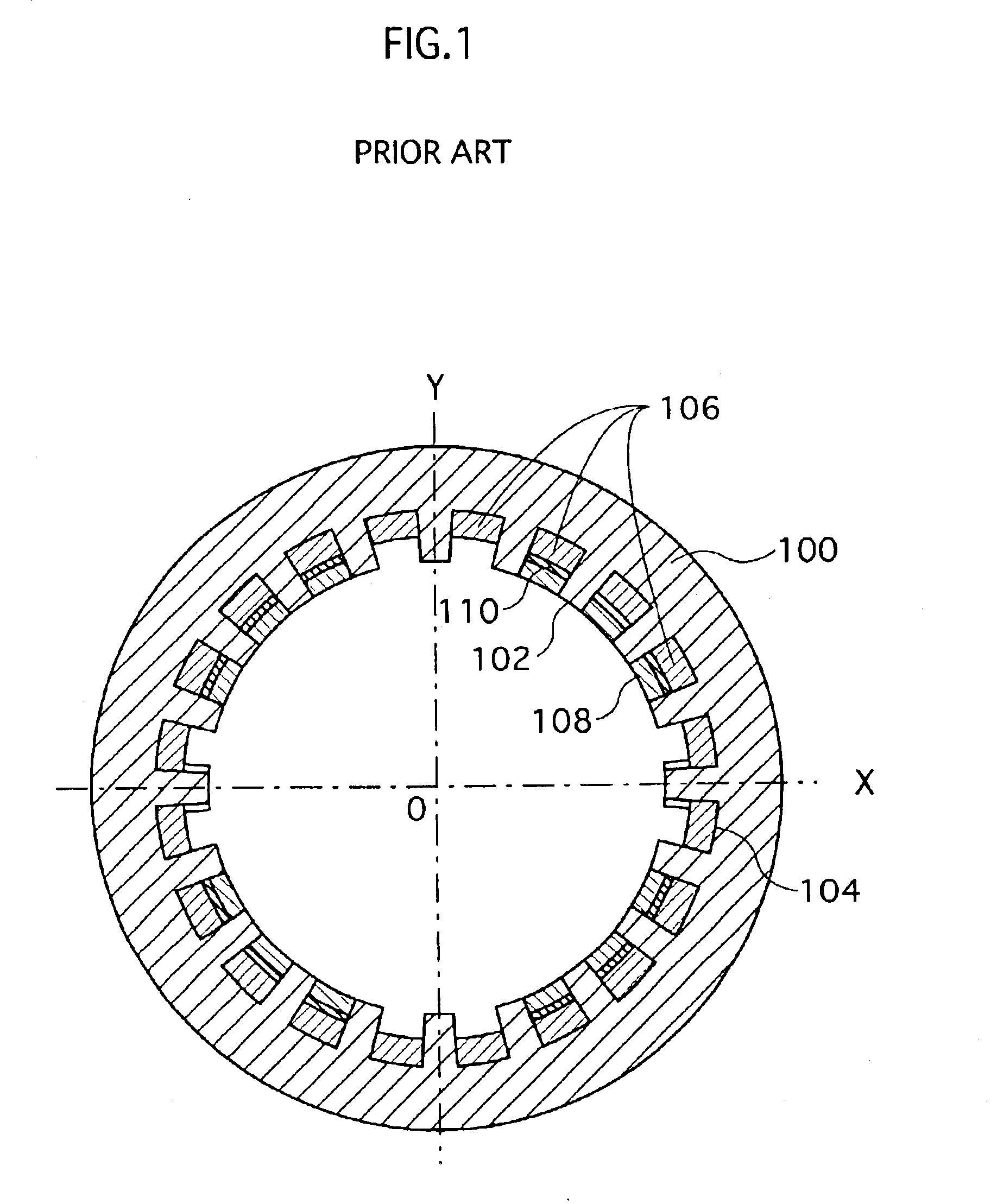
[0006]A deflection yoke with such arrangements has the following advantageous effects over a deflection yoke including a ferrite core that has a smooth inner wall without ridges and slots: The deflection sensitivity is improved because it is possible to position the ferrite core closer to the cathode ray tube, through which the electron beams pass. Also, it is possible to reduce eddy-current loss and inhibit heat generation of the deflection yoke because the magnetic flux is less likely to have a flux linkage with the deflection coils. Consequently, it is possible to save electric energy at the deflection yoke.
[0007]In recent years, energy-saving techniques have been an issue in various fields in view of the problems of environmental destruction. The field of CRT (Cathode Ray Tube) devices is not an exception. There are demands for further reduction in electric power consumption even with slot-core type deflection yokes that are already characterized with their lower electric power consumption.SUMMARY OF THE INVENTION
[0008]A first object of the present invention is to provide a deflection yoke that includes a slot core,and is more effective in energy-saving.
[0009]A second object of the present invention is to provide a CRT device comprising such a deflection yoke.
[0010]It is possible to achieve the first object of the present invention with a deflection yoke provided on an external surface of an evacuated envelope of a cathode ray tube, comprising: a tube-shaped core that is made of a magnetic material, and has, on an inner wall thereof, a plurality of ridges each of which extends along a tube axis direction of the cathode ray tube, the plurality of ridges being arranged circumferentially at predetermined intervals and there by forming a plurality of slots; a vertical deflection coil that is wound so that part of its length is disposed in one or more of the slots of the core; and a horizontal deflection coil that is wound so that part of its length is disposed in one or more of the slots of the core, wherein the slots include (a) first slots in which one of the horizontal deflection coil and the vertical deflection coil is disposed and (b) second slots in which both of the horizontal deflection coil and the vertical deflection coil are disposed, and a bottom of each first slot is, for part or all of a length of the slot, closer to the external surface of the evacuated envelope than a bottom of each second slot is.
[0011]It is possible to achieve the second object of the present invention with a cathode ray tube device including a cathode ray tube and a deflection yoke provided on an external surface of an evacuated envelope of the cathode ray tube, the deflection yoke comprising: a tube-shaped core that is made of a magnetic material, and has, on an inner wall thereof, a plurality of ridges each of which extends along a tube axis direction of the cathode ray tube, the plurality of ridges being arranged circumferentially at predetermined intervals and thereby forming a plurality of slots; a vertical deflection coil that is wound so that part of its length is disposed in one or more of the slots of the core; and a horizontal deflection coil that is wound so that part of its length is disposed in one or more of the slots of the core, wherein the slots include (a) first slots in which one of the horizontal deflection coil and the vertical deflection coil is disposed; and (b) second slots in which both of the horizontal deflection coil and the vertical deflection coil are disposed, and a bottom of each first slot is closer to an external surface of the cathode ray tube than a bottom of each second slot is.

Problems solved by technology

In recent years, energy-saving techniques have been an issue in various fields in view of the problems of environmental destruction.

Method used


Image

  • Deflection yoke and CRT device
  • Deflection yoke and CRT device
  • Deflection yoke and CRT device

Examples


Embodiment Construction

[0024]The following describes embodiments of the present invention with reference to the drawings.

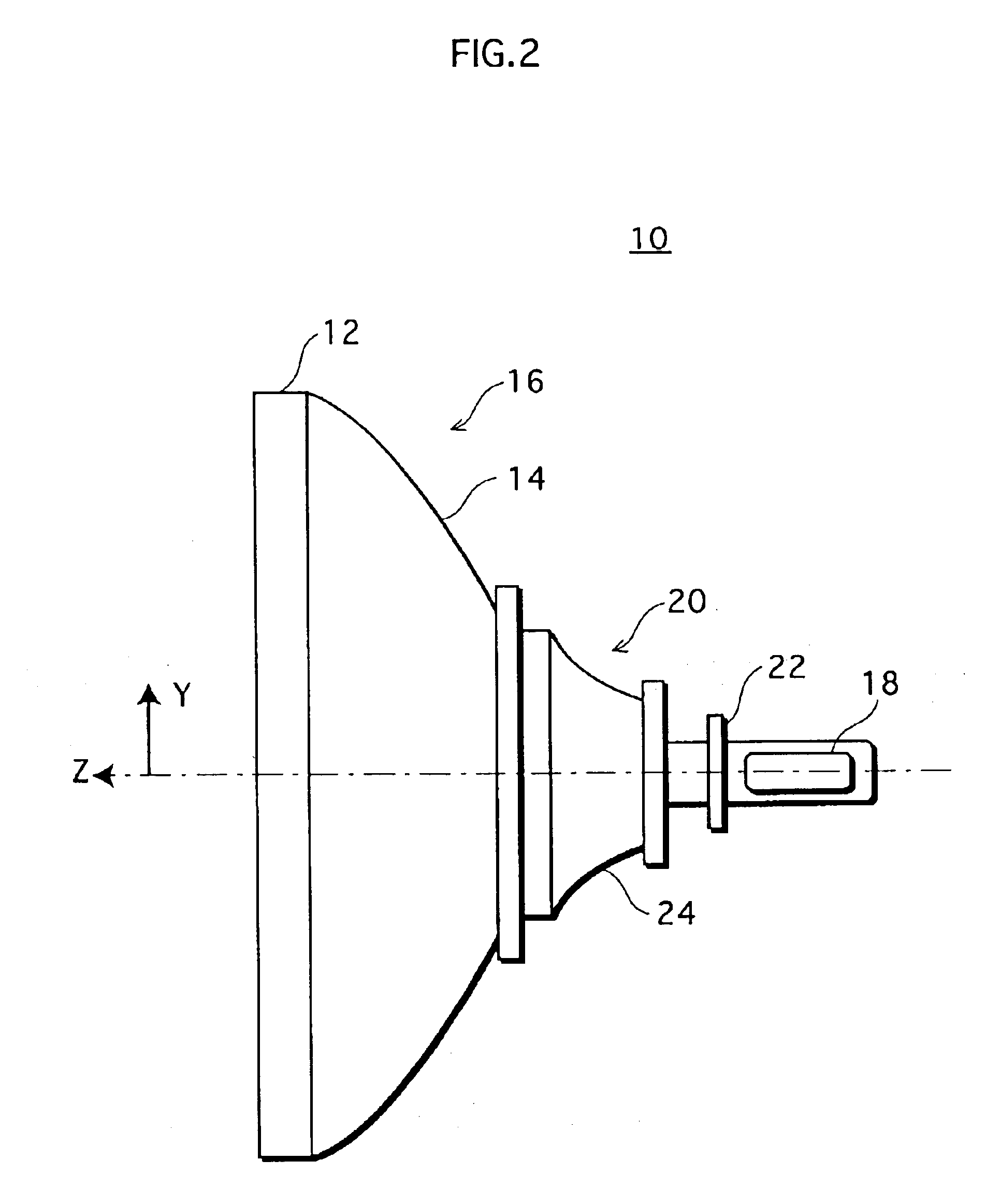
[0025]FIG. 2 is a schematic side view of a color CRT device 10 of an embodiment. The color CRT device 10 comprises: an evacuated envelope 16 in which (a) a front flat panel 12 whose inner surface has a phosphor screen formed thereon and (b) a funnel 14 are joined together; an electron gun 18 disposed in the neck of the funnel 14; a deflection yoke 20 disposed on the external surface of the funnel 14; and a convergence yoke 22. The funnel 14 is literally in the shape of a funnel. The external shape of the funnel 14 in a cross section is substantially in the shape of a pyramid that makes a smooth transition from the neck with a circular cross section to the front flat panel 12 with a substantially rectangular cross section. FIG. 2 merely shows the positional relationship among the aforementioned members, and the members such as the deflection yoke 20 are illustrated in very simplified for...


PUM

PropertyMeasurementUnit
depthaaaaaaaaaa
depthaaaaaaaaaa
depthaaaaaaaaaa

Abstract

The invention provides a deflection yoke comprising: a tube-shaped core made of a magnetic material that has on its inner wall, ridges each of which extends along the CRT axis direction, the ridges being arranged circumferentially at intervals and thereby forming slots; a vertical deflection coil wound so that part of its length is disposed in the slots; and a horizontal deflection coil wound so that part of its length is disposed in the slots, wherein the slots include (a) first slots in which one of the horizontal deflection coil and the vertical deflection coil is disposed and (b) second slots in which both of the deflection coils are disposed, and the bottom of each first slot is, for part or all of the length of the slot, closer to the external surface of the evacuated envelope than the bottom of each second slot is.

Description

[0001]This application is based on the application No. 2002-167268 filed in Japan, the contents of which are hereby incorporated by reference.BACKGROUND OF THE INVENTION[0002]1. Field of the Invention[0003]The present invention relates to CRT (Cathode Ray Tube) devices used for TVs and computer displays, and deflection yokes used in such CRT devices, particularly to the structures of the deflection yokes.[0004]2. Description of the Related Art[0005]FIG. 1 is a cross section of a ferrite core, generally called a slot core, being sectioned at a plane perpendicular to the Z axis (the tube axis). The ferrite core 100 in the deflection yoke has, on the inner wall thereof, a plurality of ridges 102 each of which protrudes substantially toward the Z axis (positioned at the center 0) and extends along the Z axis direction, the plurality of ridges 102 being arranged circumferentially. A vertical deflection coil 106 and a horizontal deflection coil 108 are wound so as to be in each slot 104 f...

Claims


Application Information

Patent Timeline
Patent Type & Authority Patents(United States)
IPC IPC(8): H01F7/00G09G1/28H01J29/76
CPCH01J29/762H01J2229/7031H01J29/76
Inventor TANIWA, KENICHIRO
Owner PANASONIC CORP
Learn More