Eureka AIR delivers breakthrough ideas for toughest innovation challenges, trusted by R&D personnel around the world.

Multi-opening heat-dissipation device for high-power electronic components

a heat dissipation device and electronic component technology, applied in the direction of liquid fuel engines, lighting and heating apparatus, instruments, etc., can solve the problems of affecting the performance and life of electronic components other than the cpu, affecting the performance and life of electronic components, and affecting the performance of electronic components. performance and lifetim

Inactive Publication Date: 2005-07-05
VIA TECH INC
View PDF4 Cites 39 Cited by
  • Summary
  • Abstract
  • Description
  • Claims
  • Application Information

AI Technical Summary

Benefits of technology

The present invention is a heat-dissipation device for high-power electronic components. It has multiple openings that allow cool air to flow to both the topside and bottom side of the circuit board, where the electronic components are mounted. The device also has a fan to create forced convection to cool the components. This design improves heat dissipation without increasing the size of the device.

Problems solved by technology

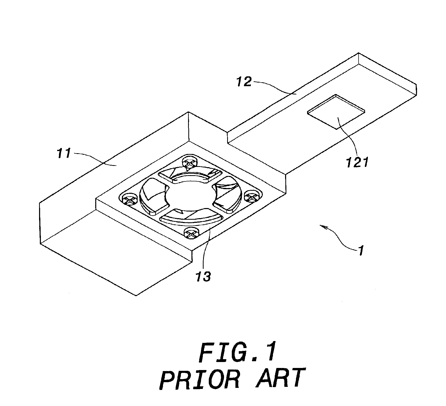
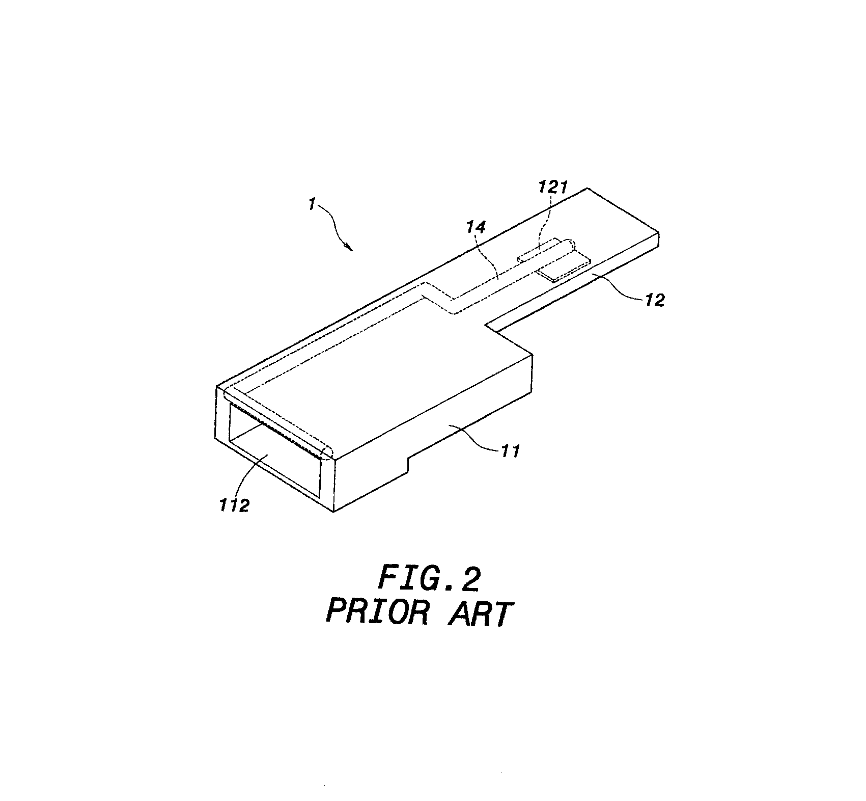
As a result, the components found inside notebook computers and portable appliances are closely packed, resulting impeded air circulation.
More importantly, notebook computers and portable appliances cannot use axial fans to remove heat from their cases, as found in desktop computers.
As a result, the performance and lifetime of the electronic components other than the CPU (31) can be deteriorated due to high temperature.
As can be seen from above description, the notebook computer has limited space for the incorporation of a heat-dissipation device.
The redesign job is time consuming and costs a lot.
The provision of heat-dissipation device to simultaneously solve the heat-dissipation problem for the components on both sides of the circuit board (3) while keeping the size and form factor is a problem that requires a solution.

Method used


Image

  • Multi-opening heat-dissipation device for high-power electronic components
  • Multi-opening heat-dissipation device for high-power electronic components
  • Multi-opening heat-dissipation device for high-power electronic components

Examples


Embodiment Construction

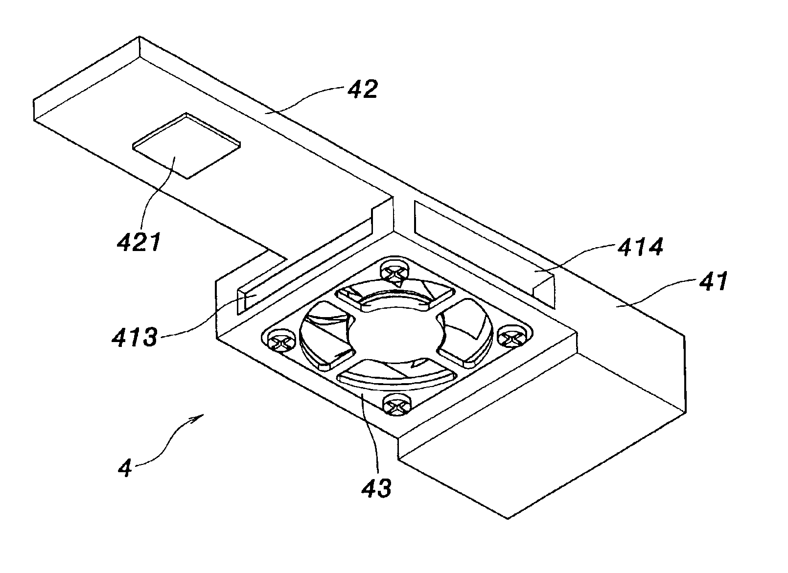
[0020]FIG. 4 shows the perspective view of the present invention. The present invention is intended to provide a multi-opening heat-dissipation device for a high-power electronic apparatus 4, which comprises a body (41), an extension (42) extending from a right top wall of the body (11), a fan (43) and a plurality of openings.

[0021]With reference to FIGS. 4 to 6, the heat-dissipation device (4), according to the first embodiment of the present invention, has a body (41) having a cavity (411) therein and the cavity (411) has a primary opening (412) on left side thereof. The body (41) has a radial fan (13) mounted on a bottom aperture thereof. A heat pipe (44) is provided in the heat-dissipation device (4) and is embedded in both the extension (42) and the body (41). A thermal interface (421) is provided on a bottom of the extension (42) in contact with the high-power electronic component, such as a CPU (31) to transfer heat from the electronic component to the heat pipe (44). Moreove...


PUM


Abstract

A multi-opening heat-dissipation device for high-power electronic components includes a body, an extension extended from the body, and a radial fan. The radial fan is mounted on a bottom aperture of the body. The body further comprises a primary opening on a first face and a cavity communicating between the bottom aperture and the primary opening as a wind path. The body further includes at least one additional opening on a second face of the body. The at least one additional comprises a second opening faces a circuit board on which a high-power electronic component is mounted. The cool air can flow to at least one of the topside and bottom side of the circuit board through the second opening and cool the high-power electronic components directly.

Description

FIELD OF THE INVENTION[0001]The present invention relates to a multi-opening heat-dissipation device for high-power electronic components, and more specifically to a multi-opening heat-dissipation device for high-power electronic components having better heat-dissipation effects without increasing the form factor thereof.BACKGROUND OF THE INVENTION[0002]Conventional notebook computers and portable appliances are developed to be more compact in size. As a result, the components found inside notebook computers and portable appliances are closely packed, resulting impeded air circulation. More importantly, notebook computers and portable appliances cannot use axial fans to remove heat from their cases, as found in desktop computers. Therefore, conventional notebook computers and portable appliances generally use a remote heat exchanger to provide a heat-dissipation solution. The heat generated by notebook computers and portable appliances is removed through thermal conduction or forced...

Claims


Application Information

Patent Timeline
Patent Type & Authority Patents(United States)
IPC IPC(8): G06F1/20H05K7/20
CPCG06F1/203
Inventor KU, SHIH-CHANG
Owner VIA TECH INC
Why Eureka
Eureka Blog
Learn More