Method and apparatus for matching positions of images

a technology of matching position and image, applied in the field of methods and apparatus for matching position of images, can solve the problems of shifting between images, difficult to find the difference in the manner described, and difficult to find the difference between images, so as to achieve the effect of suppressing the shift between two images to be compared with each other and accurately performing position matching

Inactive Publication Date: 2005-07-05
FUJIFILM HLDG CORP +1
View PDF8 Cites 30 Cited by
  • Summary
  • Abstract
  • Description
  • Claims
  • Application Information

AI Technical Summary

Benefits of technology

[0013]The primary object of the present invention is to provide a method of matching positions of images, wherein a shift between two images to be compared with each other is suppressed more reliably than with conventional image position matching techniques, and position matching is performed accurately.

Problems solved by technology

However, it is not easy to find the difference between the images, which are merely located so as to stand side by side with each other.
Particularly when the difference is small, it is difficult to find the difference in the manner described above.
In such cases, ordinarily, a shift occurs between the two acquired images due to a deviation in orientation of the object during the image recording operation, error, and the like.
However, for example, in cases where image patterns of similar textures are embedded in adjacent local area limited regions as in the cases of rib image patterns in chest radiation images, the approximate position matching processing described above has the problems in that a shift often remains between certain local area limited regions.

Method used


Image

  • Method and apparatus for matching positions of images
  • Method and apparatus for matching positions of images
  • Method and apparatus for matching positions of images

Examples


first embodiment

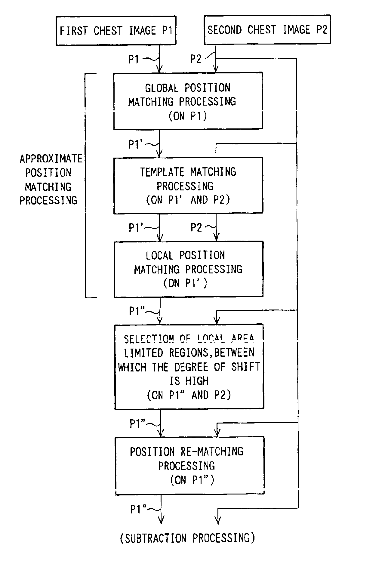
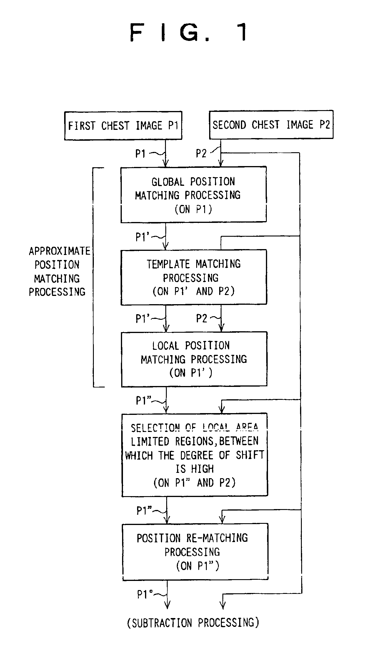
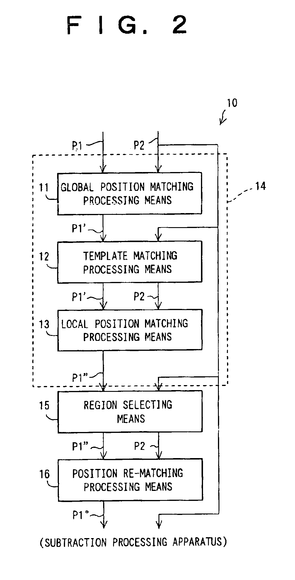
[0095]FIG. 1 is a flow chart showing a processing flow in an embodiment of the method of matching positions of images in accordance with the present invention. FIG. 2 is a block diagram showing the apparatus for matching positions of images in accordance with the present invention, which carries out the processing flow shown in FIG. 1. FIGS. 3A and 3B are schematic views showing two images P1 and P2, whose positions are to be matched with each other by the embodiment of FIG. 2. A first image P1 and a second image P2 are chest images (radiation images) of a single same patient, which images have been recorded at different points of time. The first image P1 is a past image, which has been recorded at a point of time earlier than the recording of the second image P2. The second image P2 is a current image, which is newer than the first image P1. The first image P1 and the second image P2 are the images to be subjected to temporal subtraction processing, wherein a subtraction process is...

second embodiment

[0129]More specifically, as illustrated in FIG. 17, the staged template matching processing means 16a in the second embodiment performs the processing described below.

[0130](1) As for the second image P2 acting as the reference image, with respect to each ROI in the second image P2, the staged template matching processing means 16a sets the first template region TR (one of TR1, TR2, . . . ), which has its center point at the center point having coordinates (x0, y0) in the ROI. By way of example, the first template region TR may have a rectangular shape having a size of 80 pixels (in the vertical direction)×80 pixels (in the horizontal direction). Also, as for the first image P1″, with respect to each ROI in the first image P1″, the staged template matching processing means 16a sets the first search region RR (one of RR1, RR2, . . . ), which has its center point at the same coordinates (x0, y0) as the coordinates of the center point of the first template region TR and is larger than ...


PUM


Abstract

Approximate position matching processing is firstly performed with respect to entire areas of two images of a single same object. Selection is then made to find local area limited regions, between which a degree of shift is high, in the two images, whose positions have been approximately matched with each other by the approximate position matching processing. Position re-matching processing is then performed with respect to at least the local area limited regions, which have thus been selected. The approximate position matching processing may be global position matching processing, local position matching processing, or a combination of the global position matching processing and the local position matching processing.

Description

BACKGROUND OF THE INVENTION[0001]1. Field of the Invention[0002]This invention relates to a method and apparatus for matching positions of images. This invention particularly relates to an improvement in position matching of two images of a single same object.[0003]2. Description of the Related Art[0004]Techniques for comparing at least two images of a single same object, finding a difference between the images, and making an examination of the object, or the like, in accordance with the difference between the images have heretofore been conducted in various fields.[0005]For example, in the fields of production of industrial products, there have heretofore been conducted techniques for comparing an image of a certain product, which image has been recorded when the product is in a state of a new article, and an image of the product, which image has been recorded after a durability test has been made on the product, paying attention to part of the product, at which the difference betw...

Claims


Application Information

Patent Timeline
Patent Type & Authority Patents(United States)
IPC IPC(8): A61B6/00G06T3/00G06T3/20G06T3/60G06K9/00G06T7/60G06T1/00G06T7/00G06T3/40
CPCG06T7/0026G06T7/0028G06T2207/30008G06T2207/30061G06T7/32G06T7/33
Inventor OOSAWA, AKIRA
Owner FUJIFILM HLDG CORP
Why Eureka
Try Eureka