Impedance matching switch circuit, impedance matching switch circuit module, and impedance matching circuit module

Active Publication Date: 2014-11-20
MURATA MFG CO LTD
View PDF2 Cites 0 Cited by
  • Summary
  • Abstract
  • Description
  • Claims
  • Application Information

AI Technical Summary

Benefits of technology

[0029]With this configuration, isolation between the first matching terminal and the second matching terminal is ensured. As a result, impedance matching is performed more accurately.
[0030]Various preferred embodiments of the present invention

Problems solved by technology

However, an impedance matching circuit defined by a fixed circuit pattern including only inductors and capacitors allows impedance matching to be performed in a limited frequency band and, thus, it is not easy to achieve low-loss transmission of high-frequency signals in the above-described plurality of bands.
However, in the high-frequency module disclosed in Japanese Unexamined Patent Application Publication No. 2003-179426, widening of a band cannot be achieved by using a single LC resonant circuit since there is an influence from the band pass characteristics of the LC resonant circuit.
Thus, when t

Method used


Image

  • Impedance matching switch circuit, impedance matching switch circuit module, and impedance matching circuit module
  • Impedance matching switch circuit, impedance matching switch circuit module, and impedance matching circuit module
  • Impedance matching switch circuit, impedance matching switch circuit module, and impedance matching circuit module

Examples


Embodiment Construction

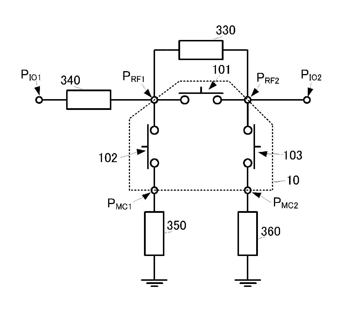
[0047]An impedance matching switch circuit module and an impedance matching circuit module according to a first preferred embodiment of the present invention will be described with reference to the accompanying drawings.

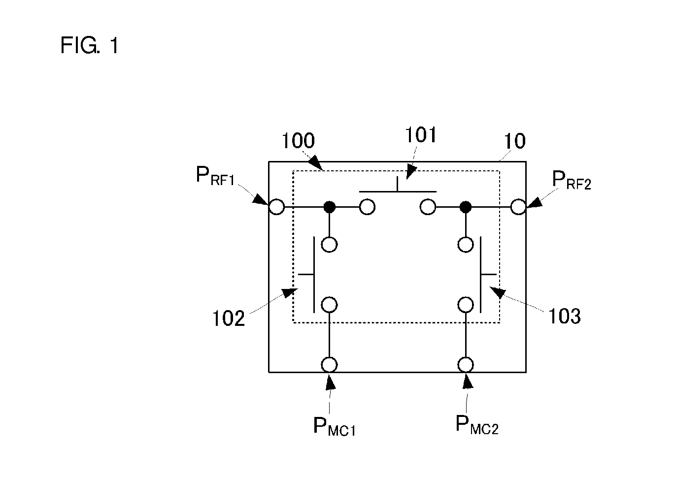
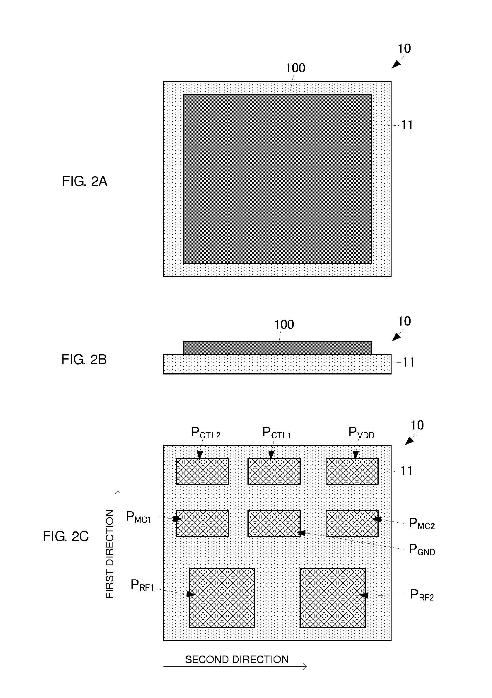
[0048]FIG. 1 illustrates an equivalent circuit of the impedance matching switch circuit module according to the first preferred embodiment of the present invention. FIGS. 2A to 2C illustrate external views of the impedance matching switch circuit module according to the first preferred embodiment of the present invention.

[0049]Referring to FIG. 1, from the viewpoint of the configuration of a circuit, an impedance matching switch circuit module 10 includes a π-type circuit including a first switch device 101, a second switch device 102, and a third switch device 103. The first, second, and third switch devices 101, 102, and 103 are preferably SPST (Single-Pole, Single-Throw) switches, for example, which are controlled so as to be in an on state (conducting state) or a...


PUM


Abstract

An impedance matching switch circuit module includes a first switch device connected to first and second high-frequency input/output terminals, a second switch device connected between the first high-frequency input/output terminal and a first matching terminal, and a third switch device connected between the second high-frequency input/output terminal and a second matching terminal. Impedance matching elements having appropriately set element values (inductances or capacitances) are connected to the first and second high-frequency input/output terminals and the first and second matching terminals, and on/off control is performed for the first, second, and third switch devices.

Description

BACKGROUND OF THE INVENTION[0001]1. Field of the Invention[0002]The present invention relates to impedance matching circuit modules configured to perform impedance matching between an antenna and a high-frequency front end unit, and also relates to impedance matching switch circuit modules included in the impedance matching circuit modules.[0003]2. Description of the Related Art[0004]Wireless communication terminals, such as cellular phones, include an antenna for transmitting / receiving high-frequency signals to / from the outside and a high-frequency front end unit for performing transmission processing and reception processing for high-frequency signals. If impedance matching is not performed between the antenna and high-frequency front end unit in the frequency band of transmitted / received high-frequency signals, the high-frequency signals cannot be transmitted between the antenna and the high-frequency front end unit with a low loss. Thus, in general, an impedance matching circuit...

Claims


Application Information

Patent Timeline
IPC IPC(8): H01P1/10H03H7/38
CPCH03H7/38H03H7/40H01H59/0009H01P1/28
Inventor WASHIMORI, TADASHI
Owner MURATA MFG CO LTD
Why Eureka
Try Eureka