Phased array blade antenna assembly

a blade array and blade array technology, applied in the direction of antennas, antenna adaptation in movable bodies, antenna feed intermediates, etc., can solve the problems of reducing the effective radiated power (erp) performance, generating adverse antenna impedance variations, and reducing optimal gain, so as to improve the impedance matching performance characteristics, improve the effective radiated power, and improve the lateral target coverage

Active Publication Date: 2007-10-09
THE GOVERNMENT OF THE UNITED STATES OF AMERICA AS REPRESENTED BY THE SEC OF THE NAVY NAVAL RES LAB WASHINGTON
View PDF3 Cites 3 Cited by
  • Summary
  • Abstract
  • Description
  • Claims
  • Application Information

AI Technical Summary

Benefits of technology

[0006]The antenna design comprises a two-element phased array blade antenna (PAB) assembly which provides improved lateral target coverage with an increased effective radiated power and exhibits smooth null-free bi-directional lateral antenna patterns. Each antenna blade pair is coupled to a 180 degree hybrid divider / combiner by a semi-rigid Radio Frequency (RF) cable. Each blade set is also connected to a sub-resonant choke balun 35 shown in FIG. 1 for improved impedance matching performance characteristics.
[0007]This antenna design provides a superior antenna input Voltage Standing Wave Ratio (VSWR), smooth lateral pattern coverage, large antenna gain and Electro-Magnetic (EM) Interference suppression. Moreover, broadband antenna performance is achieved with a unique antenna blade design that not only improves the usable frequency range of the antenna, but also provides for a light weight construction that is required for most airborne antenna systems.
[0008]Another unique feature of this antenna array design is the fact that it does not require any impedance matching networks since the antenna blade construction features a 50 ohm nominal input impedance. This feature is a major antenna design simplification beneficial in reducing construction cost, increasing reliability and also reducing RF insertion loss. The transformation of an unbalanced RF input coaxial cable to a balanced dipole configuration is accomplished with two sub-resonant choke baluns, each made out of a semi-rigid RF feed cable. This approach gives the lowest cost antenna balun implementation with more than adequate performance and, most of all, maximum design simplicity. The innovative antenna blade design provides a well-behaved antenna input impedance characteristic that covers approximately 22% of the bandwidth around the center or target design frequency.

Problems solved by technology

However, most of the antennas, especially those covering lower frequency bands, provide less than optimal pattern coverage and thus reduced Effective Radiated Power (ERP) performance.
At these lower frequencies the aircraft itself becomes a large contributor to the antenna pattern distortion and produces adverse antenna impedance variations due to antenna and aircraft body proximity.
The preexisting antenna designs feature less than optimal gain and largely irregular antenna patterns in the lateral direction significantly reducing operational effectiveness.
There are no known airborne antenna designs in the prior art that will operate in the desired frequency range and avoid the detrimental interaction of the radiated fields with the airplane structure.

Method used


Image

  • Phased array blade antenna assembly
  • Phased array blade antenna assembly
  • Phased array blade antenna assembly

Examples


Embodiment Construction

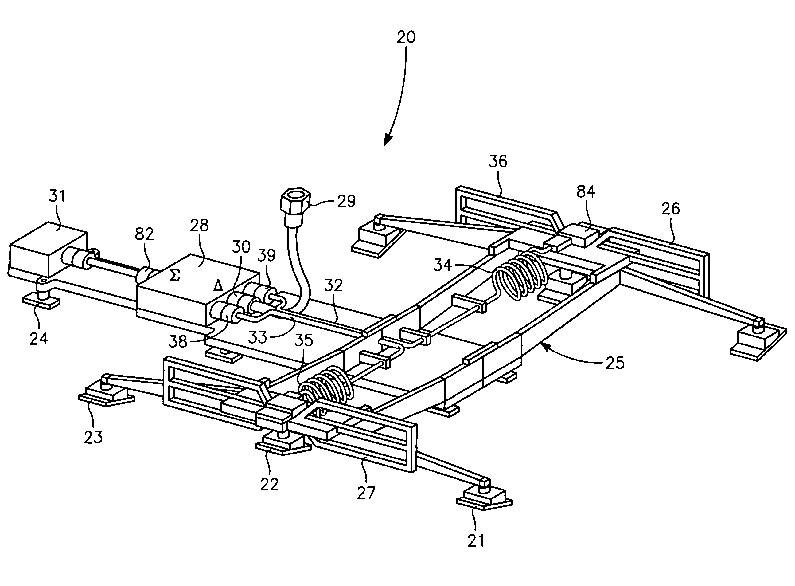
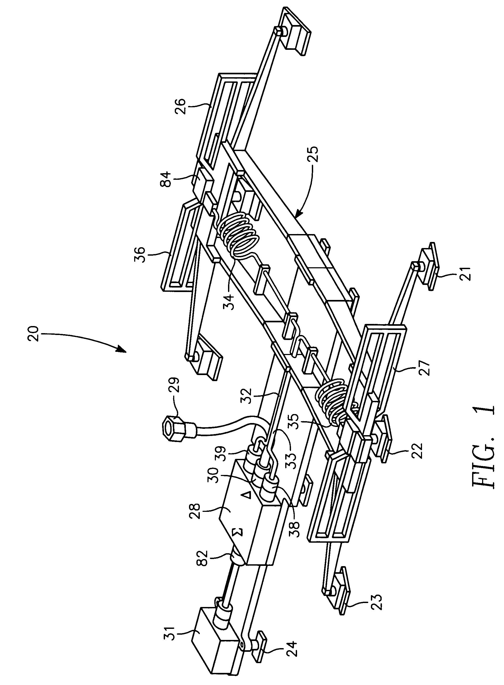
[0016]Referring to FIG. 1, the preferred embodiment of the phased array blade (PAB) antenna assembly 20 is shown in FIG. 1. The PAB antenna assembly 20 fits within the constraints of a radome intended for use on an aircraft. Clamps 21, 22, 23 and 24 are mounted on a structure made of a dielectric substrate 25 and placed as shown to anchor the PAB antenna assembly 20 to the radome. The quantity of clamps mounted on the dielectric substrate 25 can be increased in order to achieve the desired stability.

[0017]The PAB antenna assembly 20 of FIG. 1 contains two modified dipole antenna elements 26 and 27 spatially separated by a distance approximated by λ / 2. This design requires that the dipole element optimal separation be set to accommodate the center frequency of interest. Due to the radome spatial fitting constraints, a dipole elements spacing deviation from λ / 2 within + / −20% will also provide acceptable performance of the antenna assembly 20.

[0018]The RF signal that feeds the PAB ante...


PUM


Abstract

An antenna design, having two symmetrical phased array blade antenna elements which provide improved lateral target coverage with an increased effective radiated power and exhibits smooth null-free bi-directional antenna patterns. Each blade antenna element is coupled to a 180 degrees hybrid divider/combiner by a semi-rigid RF cable. Each blade antenna element is also connected to a sub-resonant choke balun for improved impedance matching and resultant distortion-less antenna patterns.

Description

BACKGROUND OF THE INVENTION[0001]1. Field of the Invention[0002]The present invention relates generally to a phased array antenna for use on an airborne platform whose mission is electronic transmission of RF signals. In particular, the present invention relates to a broadband blade array antenna system which includes a pair of modified-shape lightweight dipole blades designed to fit within a radome.[0003]2. Description of the Prior Art[0004]The industry has a number of airborne antennas used with different airborne amplifiers and covering a broad range of frequencies. However, most of the antennas, especially those covering lower frequency bands, provide less than optimal pattern coverage and thus reduced Effective Radiated Power (ERP) performance. This is mainly due to a strong interaction between the antenna radiation fields and the aircraft wings or fuselage at lower operating frequencies. At these lower frequencies the aircraft itself becomes a large contributor to the antenna ...

Claims


Application Information

Patent Timeline
Patent Type & Authority Patents(United States)
IPC IPC(8): H01Q21/12
CPCH01Q9/285H01Q1/28
Inventor ADAMSKI, PIOTR ROMAN
Owner THE GOVERNMENT OF THE UNITED STATES OF AMERICA AS REPRESENTED BY THE SEC OF THE NAVY NAVAL RES LAB WASHINGTON
Why Eureka
Try Eureka