
Method for canceling transient errors in unsynchronized digital current differential transmission line protection systems

a technology of digital current differential and transmission line protection, applied in the field of digital current differential transmission system, can solve the problems of system sensitivity ultimately limited by the accuracy of phasor measurements, application of analog line differential scheme over pilot wires was limited to a maximum distance, and not every existing current differential protection system implements the use of synchronized sampling

Inactive Publication Date: 2005-07-05
GENERAL ELECTRIC CO
View PDF6 Cites 10 Cited by
  • Summary
  • Abstract
  • Description
  • Claims
  • Application Information

AI Technical Summary

Benefits of technology

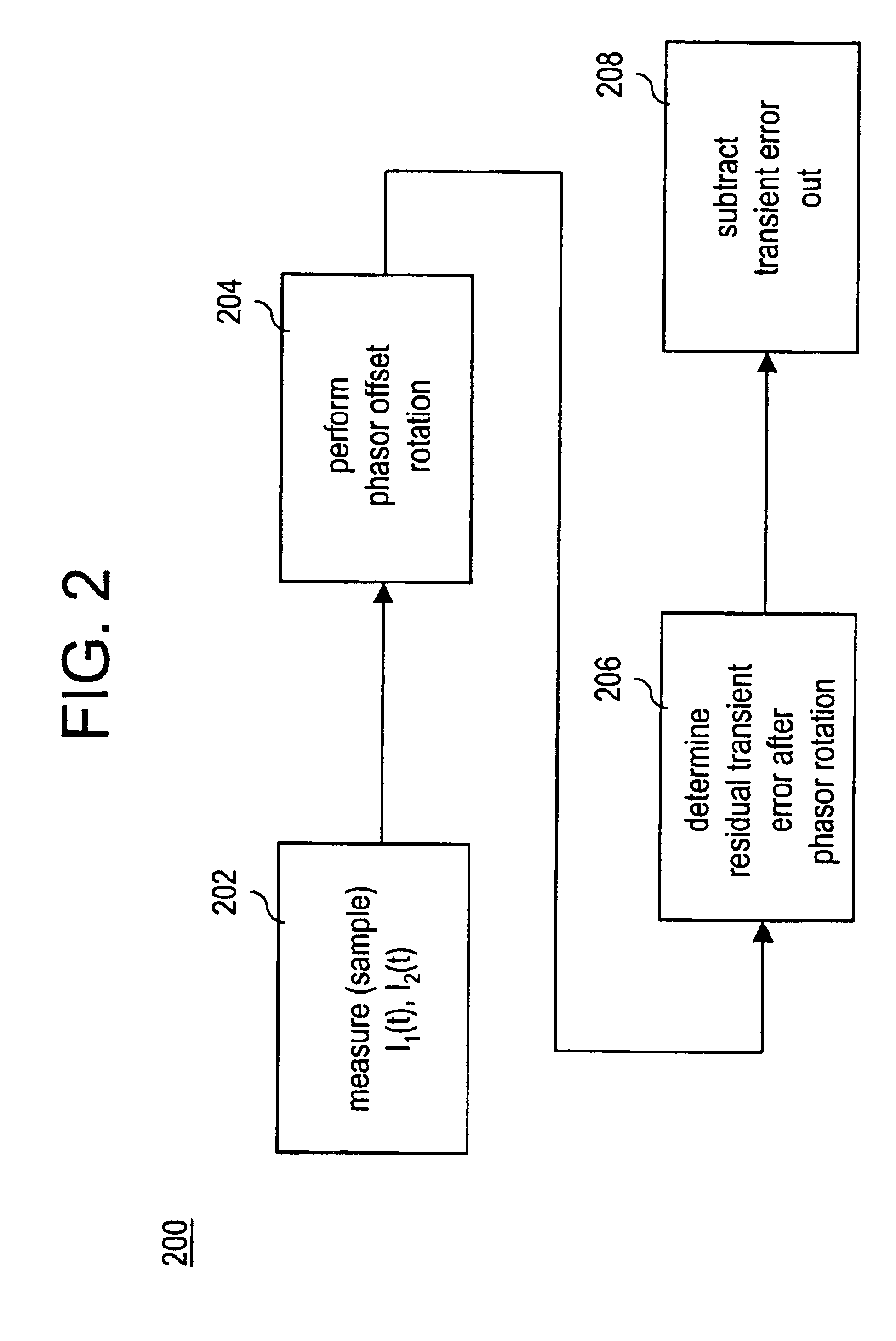
"The patent describes a method for detecting and canceling out errors in a system that measures the current in a transmission line. The method involves measuring the current at two different times and adjusting the second measurement to account for an offset between two sampling clocks. This results in a rotated second measurement. By subtracting out the residual error from the first and second measurements, the method can accurately detect and cancel out any errors in the current measurement. This can improve the accuracy and reliability of the system."

Problems solved by technology

The application of an analog line differential scheme over pilot wires was limited to a maximum distance of about 8-10 kilometers, due to several factors such as pilot wire capacitance resistance, extraneously induced voltages (e.g., ground potential rise), etc.
Because differential current is computed as the total of the phasor currents measured at the same time at all terminals, the system sensitivity is thus ultimately limited by the accuracy of those phasor measurements.
However, not every existing current differential protection system implements the use of synchronized sampling.

Method used


Image

  • Method for canceling transient errors in unsynchronized digital current differential transmission line protection systems
  • Method for canceling transient errors in unsynchronized digital current differential transmission line protection systems
  • Method for canceling transient errors in unsynchronized digital current differential transmission line protection systems

Examples


Embodiment Construction

[0011]Disclosed herein is a method for canceling transient errors in unsynchronized digital current differential transmission line protection systems. Briefly stated, in those classes of digital current differential transmission line protection systems in which sampling is not synchronized, two error components are calculated in improving the sensitivity in the unsynchronized current sampling. The first error component (as is well known) is a phasor rotation to compensate for a sampling clock shift for a periodic current waveform. However, there is also a second error component that results from a transient effect and can cause misoperation of this type of protection system under certain transient conditions, such as during line energization, for example.

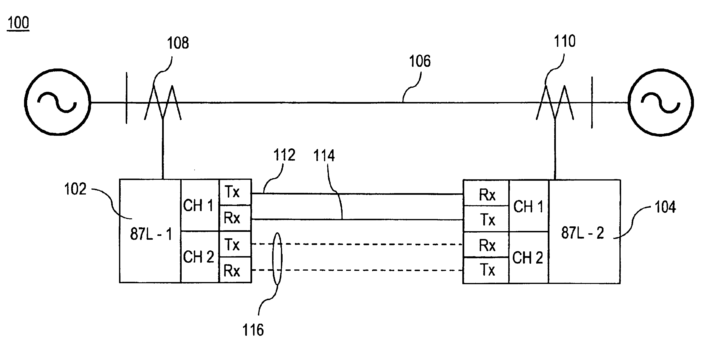
[0012]Referring initially to FIG. 1, there is shown a schematic diagram of an exemplary transmission protection, digital current differentiation system 100. A pair of current differential relays 102, 104 compare the current entering...


PUM


Abstract

A method for determining transient errors in an unsynchronized, digital current differential transmission line protection system includes receiving a first current phasor measurement at a time, t, and receiving a second current phasor measurement at time t. The second current phasor is adjusted so as to account for a determined offset between a first sampling clock associated with the first current phasor measurement and a second sampling clock associated with the second current phasor measurement, thereby resulting in a rotated second current phasor measurement. A residual transient error is then obtained from the rotated second current phasor measurement and the first current phasor measurement.

Description

BACKGROUND OF THE INVENTION[0001]The present disclosure relates generally to digital current differential transmission systems and, more particularly, to a method for canceling transient errors in unsynchronized digital current differential transmission line protection systems.[0002]In recent years, there has been an increased interest in the application of line differential relays to very long power transmission lines by utilities all over the world. This renewed attention to this technique is due, in large part, to the availability of digital differential relays operating over high-speed digital communication channels. The basic operating principle of current differential relaying is to calculate the difference between the currents entering and leaving a protected zone, such that a protection feature is engaged whenever the current difference exceeds a threshold level. Accordingly, line differential relaying requires that the information of the current flowing through each line te...

Claims


Application Information

Patent Timeline
Patent Type & Authority Patents(United States)
IPC IPC(8): G01R31/00G01R19/00G06F19/00G01R19/25
CPCG01R19/2513
Inventor PREMERLANI, WILLIAM J.
Owner GENERAL ELECTRIC CO
Learn More