Differential transmission circuit and information processing system

a transmission circuit and information processing technology, applied in the direction of waveguides, waveguide type devices, cross-talk/noise/interference reduction, etc., can solve the problems of increasing the cost of the case structure components, the increase of the frequency of unintentional electromagnetic radiation, and the small and steep increase of the allowable unintentional electromagnetic radiation. to achieve the effect of increasing the cos

Active Publication Date: 2012-10-25
LUMENTUM JAPAN INC
View PDF3 Cites 32 Cited by
  • Summary
  • Abstract
  • Description
  • Claims
  • Application Information

AI Technical Summary

Benefits of technology

[0025]According to the aspects of the invention, it is possible to provide the differential transmission circuit capable of suppressing unintentional electromagnetic radiation caused due to switchi

Problems solved by technology

In recent years, the intensity of allowable unintentional electromagnetic radiation has had to be small and steep with the miniaturization or integration of an apparatus.
Therefore, since processing means is used to increase the dimension accuracy in the manufacturing of the case structure components, a problem may arise in that the cost of the case structure component

Method used


Image

  • Differential transmission circuit and information processing system
  • Differential transmission circuit and information processing system
  • Differential transmission circuit and information processing system

Examples


first embodiment

[0055]A differential transmission line and an information processing system according to a first embodiment of the invention will be described.

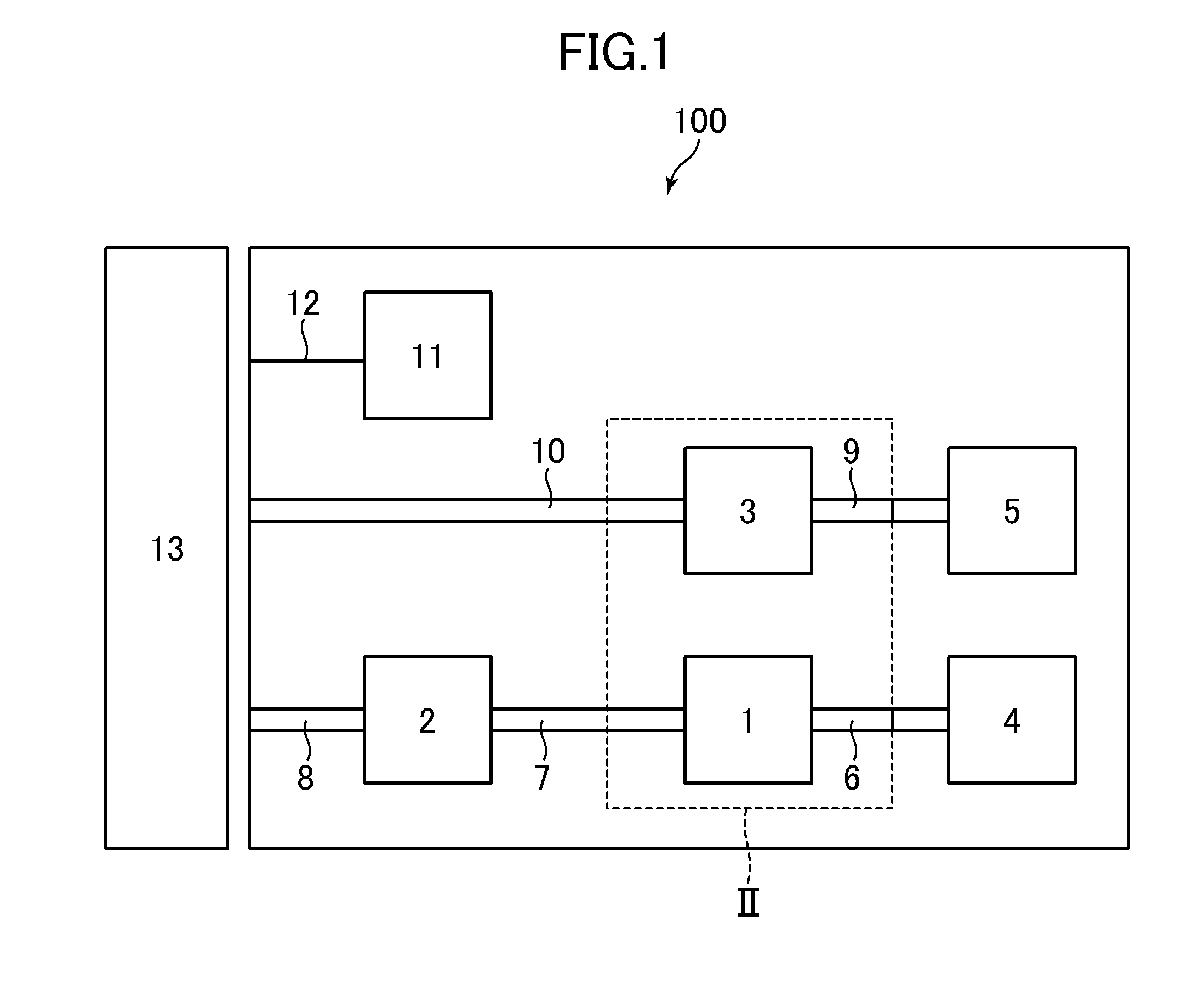
[0056]FIG. 1 is a block diagram illustrating an information processing system 100 according to the first embodiment of the invention. The information processing system 100 according to this embodiment includes a driving integrated circuit 1 (driver IC), a transmitter CDR (Clock Data Recovery) integrated circuit 2 having a CDR function, a receiver CDR integrated circuit 3, a receiver circuit 4, a transmitter circuit 5, a control unit 11, and a transmission device 13. The information processing system 100 is connected to the transmission device 13.

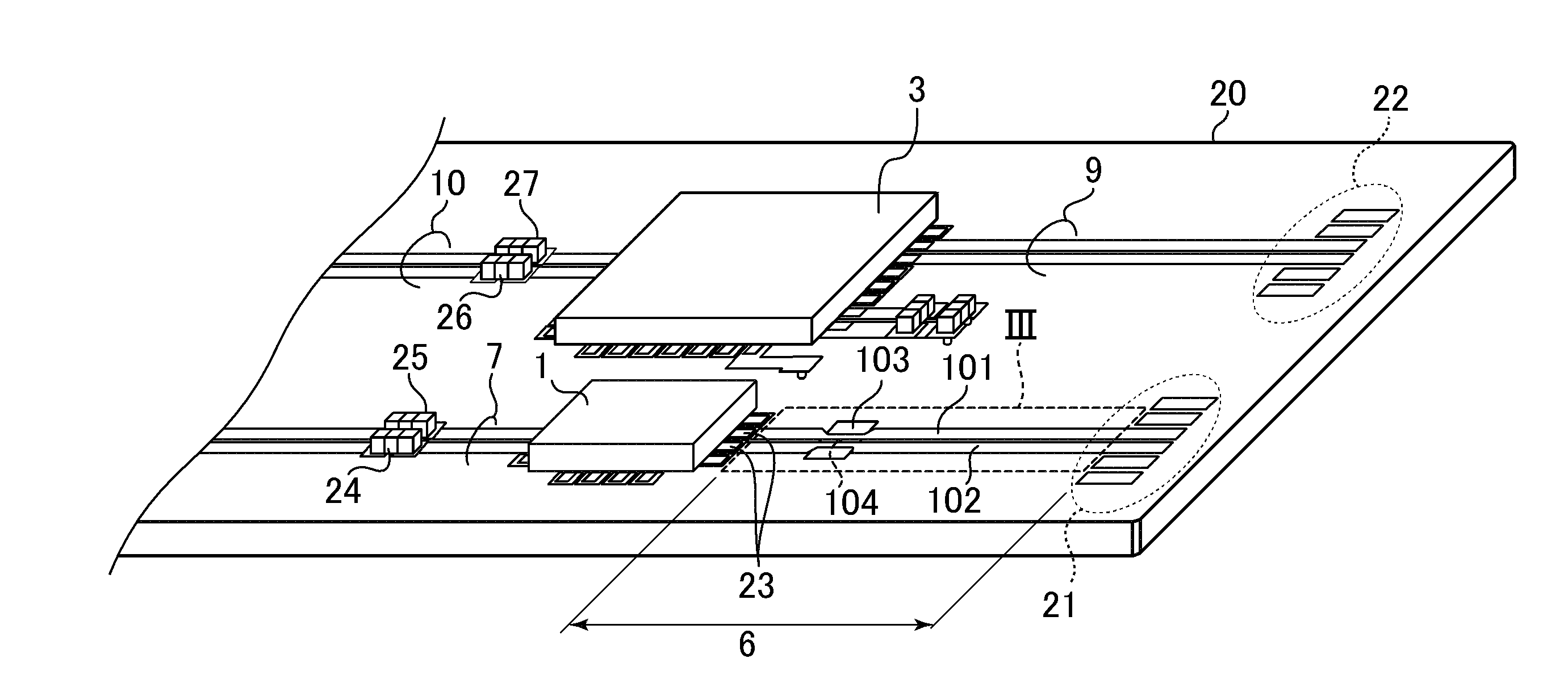
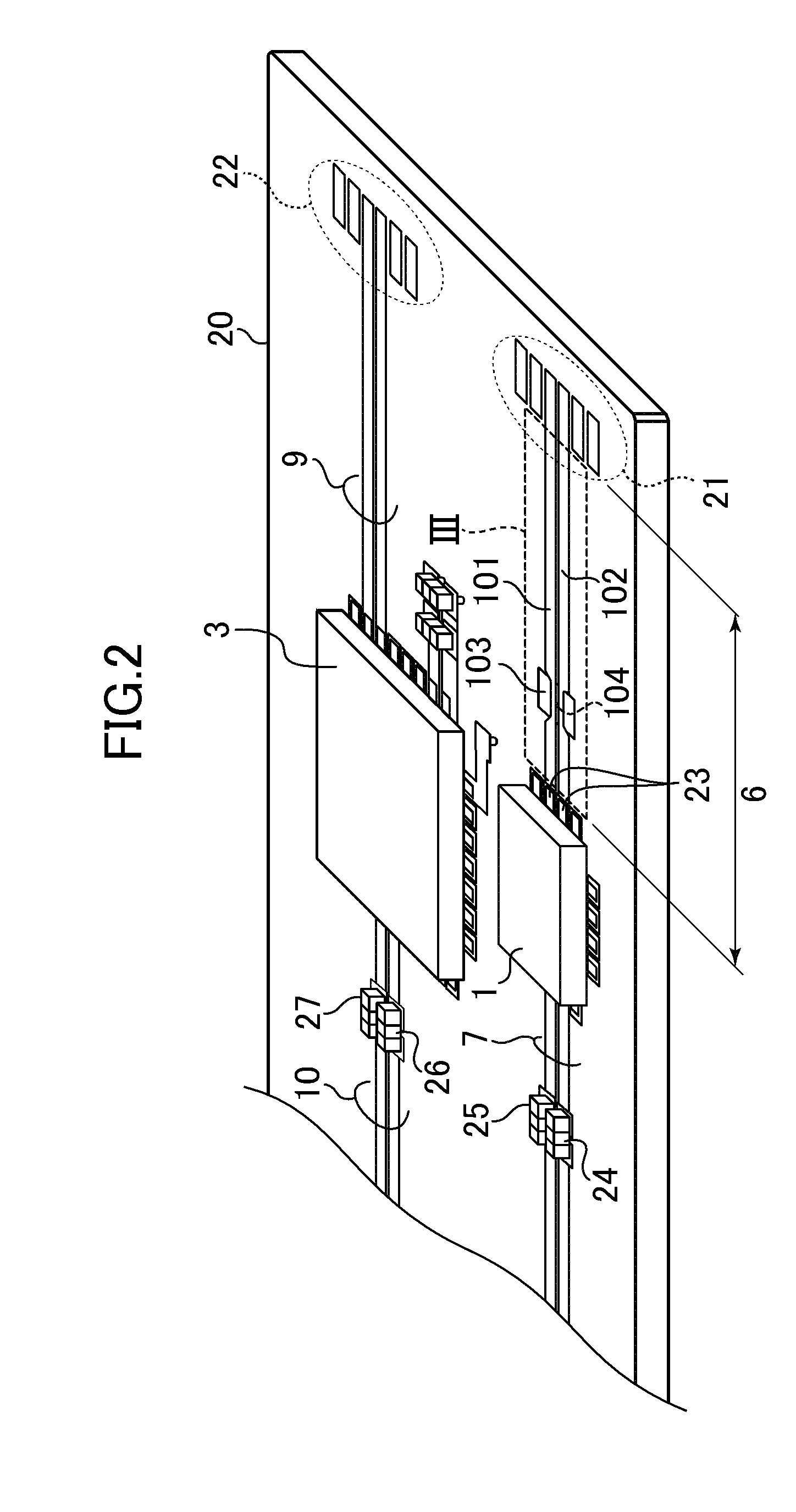
[0057]A transmission line is disposed between the driving integrated circuit land the receiver circuit 4. Here, as described below, the transmission line includes a differential transmission line 6. A transmitter-side differential output transmission line 7 is disposed between the transmitter CDR inte...

second embodiment

[0097]The basic configuration of the information processing system 100 according to a second embodiment of the invention is the same as that of the information processing system 100 according to the first embodiment. However, the configuration of the information processing system 100 according to the second embodiment is different from that of the information processing system 100 according to the first embodiment in that the desired characteristic impedance Zdiff in the differential mode of the differential transmission line 6 is 50Ω and the central frequency of the common mode band rejection filter circuit is near 10 GHz.

[0098]FIG. 10 is a top view illustrating the differential transmission line 6 according to this embodiment. As in FIG. 3, the differential transmission line 6 includes a first strip conductor 111, a second strip conductor 112, an intermediate conductive film 113, a via hole 114, and a grounded conductive layer 110. An example of the dimensions of each portion of t...

third embodiment

[0102]The basic configuration of the information processing system 100 according to a third embodiment of the invention is the same as that of the information processing system 100 according to the first embodiment. However, a differential transmission line 6 according to this embodiment is different from the differential transmission line according to the first embodiment in that the differential transmission line 6 includes two band rejection filter regions arranged in series.

[0103]FIG. 12 is a top view illustrating the differential transmission line 6 according to this embodiment. The differential transmission line 6 includes a first strip conductor 121, a second strip conductor 122, a first intermediate conductive film 123, a second intermediate conductive film 125, a first via hole 124, and a second via hole 126. Here, two band rejection filter regions are referred to as first and second band rejection filter regions, when viewed from the side (left side) of the connection pads...


PUM


Abstract

A differential transmission circuit includes a grounded conductive layer, a pair of transmission line conductors, a conductive film and a via hole which connects the grounded conductive layer to the conductive film. The differential transmission circuit further includes a straight-line region which is present in the differential transmission circuit through which a differential transmission signal output by a driving circuit is transmitted and in which the pair of transmission line conductors extends parallel so as to have a first width, and a band rejection filter region in which the pair of transmission line conductors planarly overlaps the conductive film and extends parallel so as to have a second width narrower than the first width and a common mode of the differential transmission signal is attenuated at one of the frequencies which are natural number multiples of a frequency corresponding to the predetermined bit rate.

Description

CROSS-REFERENCE TO RELATED APPLICATION[0001]The present application claims priority from Japanese application JP 2011-096377 filed on Apr. 22, 2011, the content of which is hereby incorporated by reference into this application.BACKGROUND OF THE INVENTION[0002]1. Field of the Invention[0003]The present invention relates to a differential transmission circuit and an information processing system using the differential transmission circuit, and more particularly, to a technique of suppressing unintentional electromagnetic radiation from the differential transmission circuit.[0004]2. Description of the Related Art[0005]A transmission line is used in high-speed digital transmission of serial data. For example, not single-end transmission but differential transmission is generally used to transmit serial data at a speed of hundreds or more of Mbit / s. A transmission line used for the differential transmission is a differential transmission line. In general, the differential transmission l...

Claims


Application Information

Patent Timeline
IPC IPC(8): H01P3/08H04B10/04H01P1/20
CPCH05K1/0245H05K1/0246H05K2201/09727H01P3/026H04B10/801H05K1/025H05K1/162H05K2201/10121H05K1/0218
Inventor KAGAYA, OSAMU
Owner LUMENTUM JAPAN INC
Why Eureka
Try Eureka