Novel speed reducer and speed reduction motor

A planetary reducer and geared motor technology, applied in the direction of electromechanical devices, electrical components, mechanical equipment, etc., can solve the problems of difficult consistency of precision, poor stiffness, high noise, etc., and achieve reasonable structural design, large bearing capacity, and low cost Effect

Inactive Publication Date: 2011-10-26
SHENZHEN XAMMAX TECH
View PDF10 Cites 33 Cited by
  • Summary
  • Abstract
  • Description
  • Claims
  • Application Information

AI Technical Summary

Problems solved by technology

The difference in performance is: figure 1 It is a multi-tooth contact, with strong bearing capacity, stable transmission and high transmission efficiency; figure 2 The planetary gear 3 i...

Method used


Image

  • Novel speed reducer and speed reduction motor
  • Novel speed reducer and speed reduction motor
  • Novel speed reducer and speed reduction motor

Examples


Embodiment 1

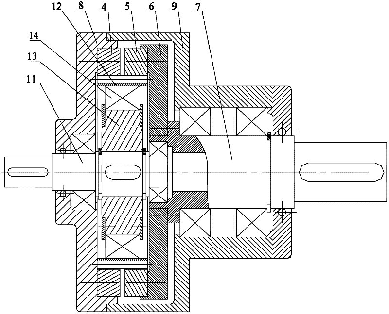
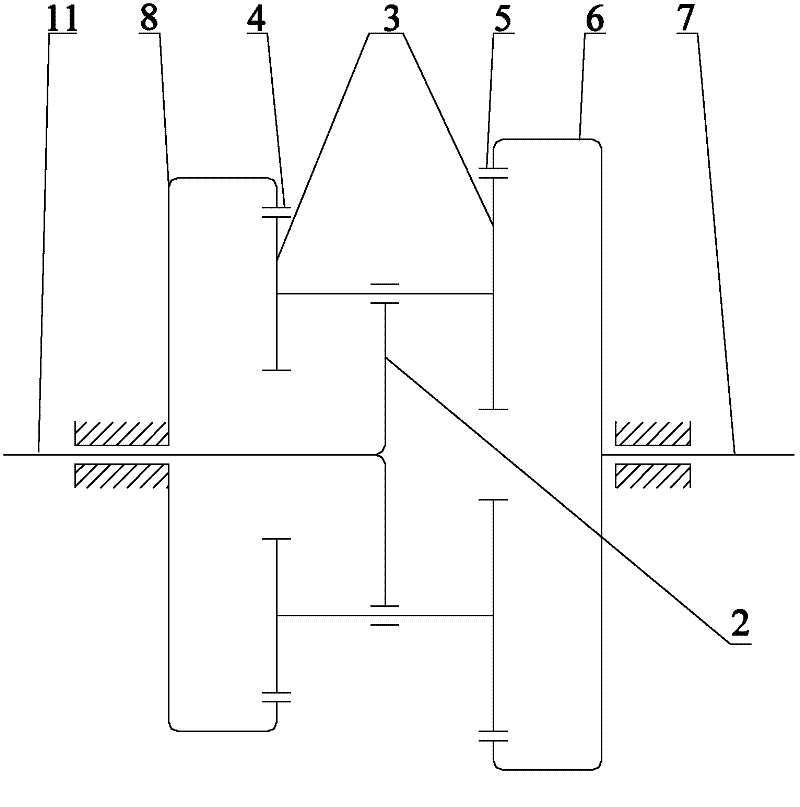
[0037] See image 3 , image 3 It is a cross-sectional view of a new type of planetary reducer provided by the present invention. among them, image 3 The new type planetary reducer shown can also be referred to as an imitation harmonic gear planetary reducer.

[0038] Such as image 3 Said, this new type of planetary reducer may include: a planetary carrier 2 fixed on the input shaft 11 and with a planetary gear 3; a fixed ring gear 4 fixed on the end cover 8, and a fixed ring 6 fixed on the coupling disc 6. An output shaft 7 is fixed on the coupling disc 6; the housing 9 is positioned on the output shaft 7 through a bearing, and the end cover 8 is positioned on the input shaft 11 through a bearing. The housing 9 is fastened to the end cover 8; the fixed internal gear ring 4 is coaxial with the input shaft 11; the movable internal gear ring 5 is coaxial with the output shaft 7; the fixed internal gear ring 4 and the moving internal gear ring 5 have the same size, but different ...

Embodiment 2

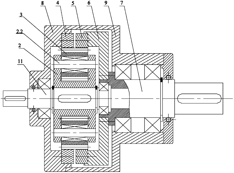
[0052] See Figure 4 , Figure 4 A cross-sectional view of a geared motor provided by the present invention. among them, Figure 4 The geared motor shown can also be referred to as a harmonic-like gear planetary geared motor.

[0053] in Figure 4 In the geared motor shown, the motor stator 1 is fixed on the end cover 8, and the end cover 8 is fastened to the housing 9; the housing 9 is fastened with a fixed internal gear ring 4, and the movable internal gear ring 5 is fixed on On the coupling disk 6, an output shaft 7 is fixed on the coupling disk 6; a planetary gear carrier 2 is fixed on the outer rotor 1.1 of the motor, and the planetary gear carrier 2 is provided with a planetary gear 3; the motor stator 1 and the The planetary carrier 2 is positioned on the output shaft 7 through bearings; the fixed internal gear 4 and the dynamic internal gear 5 have the same size and different numbers of teeth; the fixed internal gear 4 and the dynamic internal gear The ring gears 5 are c...

Embodiment 3

[0059] See Figure 7 , Figure 7 It is a cross-sectional view of another geared motor provided by the present invention. among them, Figure 7 The geared motor shown can also be referred to as a harmonic-like planetary geared hub motor for electric vehicles.

[0060] in Figure 7 The geared motor shown includes a housing 9, an end cover 8 locked at both ends of the housing 9, a motor stator 1, a motor outer rotor 1.1, and a central shaft 7.1; the motor stator 1 is fixed on the central shaft 7.1 On the outer rotor 1.1 of the motor, a planetary carrier 2 is fixed, and the planetary carrier 2 with planetary gears 3 is positioned on the central shaft 7.1 through bearings; a fixed ring gear 4 is fastened on the housing 9 , The movable inner gear ring 5 is fixed on the coupling disc 6, the inner ring of the coupling disc 6 is provided with a secondary coupling disc 6.1 fixed on the central shaft 7.1, and a unidirectional pivot is provided between the coupling disc 6 and the seconda...


PUM


Abstract

The invention discloses a novel planetary speed reducer and a speed reduction motor. The planetary speed reducer comprises a planetary wheel frame 2, a fixed ring gear 4, a moving ring gear 5, a coupling plate 6, an output shaft 7, a shell 9, an end cover 8 and an input shaft 11, wherein the planetary wheel frame 2 is fixed on the input shaft 11 and is provided with at least one planetary gear 3; the fixed ring gear 4 is fixed on the end cover 8; the moving ring gear 5 is fixed on the coupling plate 6; the output shaft 7 is fixed on the coupling plate 6; the shell 9 is positioned on the output shaft 7 through a bearing; the end cover 8 is positioned on the input shaft 11 through a bearing; the shell 9 and the end cover 8 are fastened tightly; the fixed ring gear 4 and the input shaft 11 are coaxial; the moving ring gear 5 and the output shaft 7 are coaxial; the fixed ring gear 4 and the moving ring gear 5 are same in size and different in gear quantity; and the fixed ring gear 4 and the moving ring gear 5 are parallel and coaxial, are meshed with at least one planetary gear 3 to form a novel planetary differential transmission mechanism. According to the invention, high-efficiency large speed ratio transmission can be realized, the structure is simple, the cost is low, and the application range is wide.

Description

Technical field [0001] The invention relates to the field of electromechanics, in particular to a new type of planetary reducer and reduction motor. Background technique [0002] Harmonic gear transmission includes three basic elements: wave generator, flexible wheel and rigid wheel. Among them, one of the three basic elements can be fixed arbitrarily, and one of the remaining two is active and the other is driven, which can realize deceleration or increase, and can also be transformed into two inputs and one output to form a differential transmission. If two sets of harmonic gear devices are combined to share a wave generator and a flexspline, two rigid wheels, flexsplines and wave generators with the same pitch diameter and different numbers of teeth form the new four elements, the flexspline As an intermediate transmission part, one of the remaining three components can be fixed at will, the remaining two, one is active and the other is driven, which can realize deceleration ...

Claims


Application Information

Patent Timeline
IPC IPC(8): F16H1/32F16H57/02F16H55/17F16H55/06H02K7/116
Inventor 朱正风李家俊
Owner SHENZHEN XAMMAX TECH
Why Eureka
Try Eureka