Integrated, self-powered battery monitoring device and system

a battery monitoring and self-powered technology, applied in battery/fuel cell control arrangement, cell components, instruments, etc., can solve the problem that conventional battery monitoring systems tend to be “wiring intensive”

Inactive Publication Date: 2005-07-05
GENERAL ELECTRIC CO
View PDF10 Cites 40 Cited by
  • Summary
  • Abstract
  • Description
  • Claims
  • Application Information

AI Technical Summary

Problems solved by technology

However, conventional battery monitoring systems tend to be “wiring intensive” in that each measurement point (e.g., a voltage or temperature sensor device for a given cell) generally requires at least two signal leads and two power leads for each parameter measured.

Method used


Image

  • Integrated, self-powered battery monitoring device and system
  • Integrated, self-powered battery monitoring device and system
  • Integrated, self-powered battery monitoring device and system

Examples


Embodiment Construction

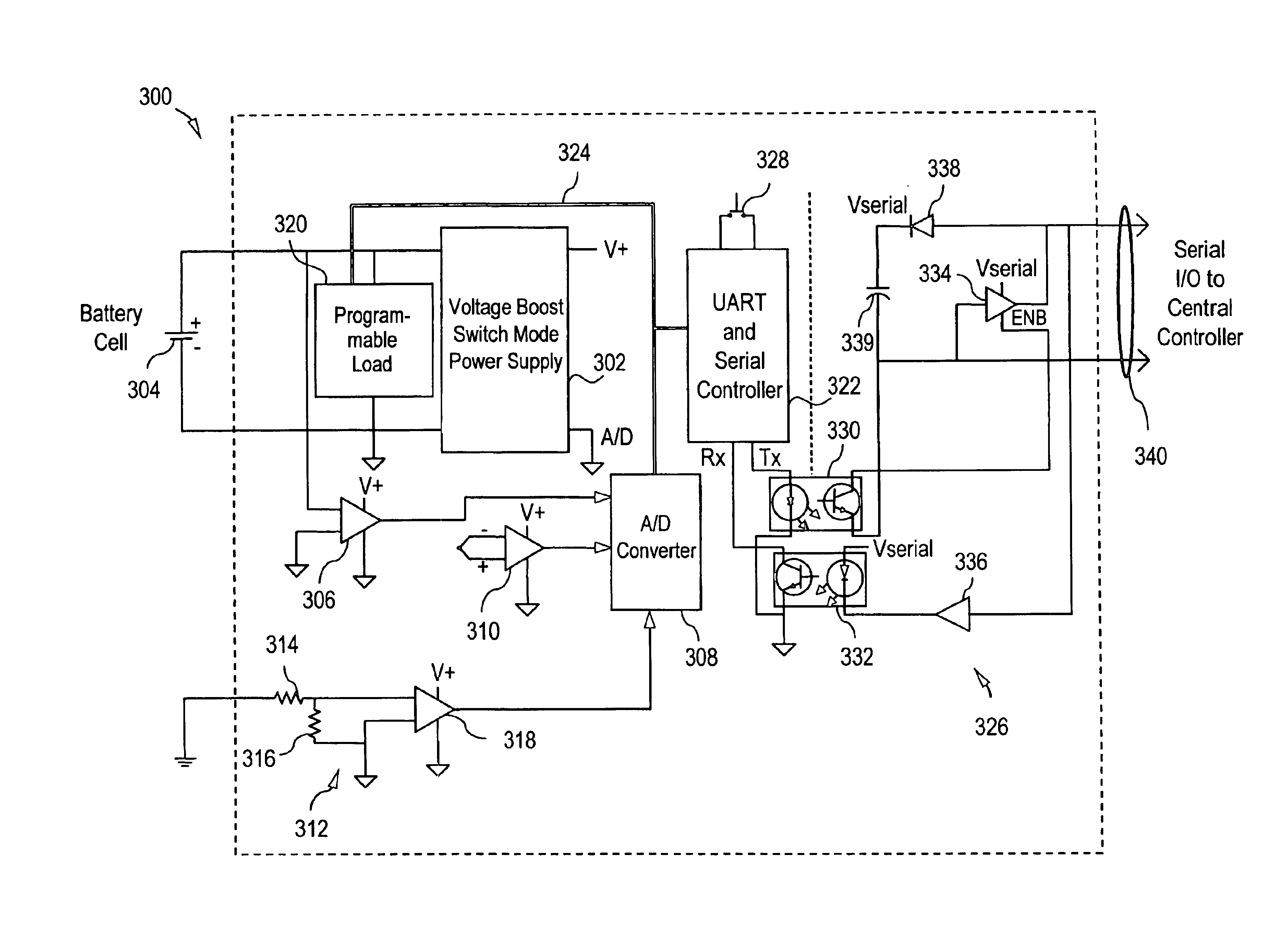
[0012]Disclosed herein is an integrated measurement and control module that connects directly to the terminals of a battery cell or jar and is used in conjunction with a central controller and monitoring system to maintain and diagnose the condition of a string of battery cells. The measurement and control module is self-powered, and contains its own serial communications interface for use with a central control system. The integration of several discrete measurement and control functions into a simple, self-powered modular component will reduce installation time over conventional battery monitor instrumentation systems, as well as decrease wiring and parts requirements.

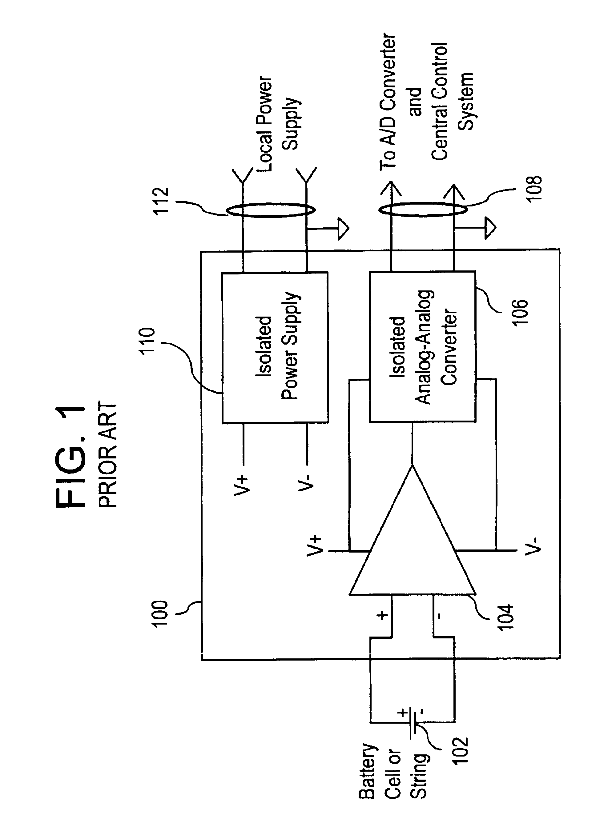
[0013]Referring initially to FIG. 1, there is shown a schematic diagram of an existing voltage transducer 100 used in conjunction with an individual battery cell 102 included within a battery string. A differential amplifier 104 is coupled to the terminals of the cell 102 and provides an output voltage signal to an i...


PUM

PropertyMeasurementUnit
operating voltagesaaaaaaaaaa
voltagesaaaaaaaaaa
voltagesaaaaaaaaaa

Abstract

An integrated battery monitoring device includes a pair of input leads for coupling across the terminals of a battery cell to be monitored and a sensor for sensing a desired battery cell parameter. A self-contained power supply has the voltage across the battery cell terminals as an input thereto, the self-contained power supply being configured for providing power to the sensor. A pair of output leads communicates data generated by the sensor.

Description

BACKGROUND OF THE INVENTION[0001]The present disclosure relates generally to battery monitoring systems and, more particularly, to an integrated battery monitoring device and system having distributed, self-powered sensors.[0002]Conventional battery installations commonly utilize a plurality of series connected battery cells in order to generate operating voltages higher than the nominal 1-3 volts typically present in an individual battery cell. In certain applications, a sufficient number of cells can be connected to achieve voltages as high as 400 volts (V) or more. Collectively, these multiple, series connected battery cells are referred to as a battery string. As a battery string is being charged, the individual cells could react differently to the charging current. In particular, it is desired that a given cell not be overcharged since this could damage the cell and perhaps even the entire battery.[0003]Accordingly, battery monitoring systems are sometimes used to periodically ...

Claims


Application Information

Patent Timeline
Patent Type & Authority Patents(United States)
IPC IPC(8): G01R31/36G06F19/00H01M50/569H02J7/00
CPCB60L3/0046B60L3/0069G01R31/3658G01R31/3696H02J7/0021H01M10/486B60L2240/545B60L2240/547B60L2240/549G01R31/3689Y02T90/16G01R31/396G01R31/364G01R31/371B60L58/10Y02T10/70Y02E60/10H02J7/0025H02J7/0048H01M50/569
Inventor CARDINAL, MARK E.KING, ROBERT DEANLYONS, JAMES PATRICK FRANCIS
Owner GENERAL ELECTRIC CO
Why Eureka
Try Eureka