Method, computer program, and device for measuring the amount injected by an injection system

a technology of injection system and injection volume, which is applied in the direction of machines/engines, electrical control, instruments, etc., can solve the problems of increasing the pressure in the gas volume and thus the volume of the test fluid, and achieving only major effort and expense, and achieves the effect of reducing the gas volume located in the measurement chamber and being easy to d

Inactive Publication Date: 2005-07-12
ROBERT BOSCH GMBH
View PDF15 Cites 12 Cited by
  • Summary
  • Abstract
  • Description
  • Claims
  • Application Information

AI Technical Summary

Benefits of technology

[0009]The method of the invention is based on the concept that the injected test fluid is essentially incompressible. The injected test fluid is normally a test oil, which especially if injection systems of internal combustion engines are to be tested has physical properties that are equivalent to those of fuel, such as Diesel fuel or gasoline. Since the total volume of the measurement chamber is constant during the injection, the gas volume located in the measurement chamber is reduced upon an injection by the volume of the injected test fluid. This reduction in the gas volume results in an increase in the pressure in the gas volume (and thus also in the volume of the test fluid). However, such a change in the pressure in the measurement chamber can easily be detected. Fmm the detected pressure change, it is then possible with the aid of the state equation for ideal gases to ascertain the applicable change in volume.

Problems solved by technology

This reduction in the gas volume results in an increase in the pressure in the gas volume (and thus also in the volume of the test fluid).
A complete evacuation of the measurement chamber before an injection can be accomplished only at major effort and expense in the normal situation.

Method used


Image

  • Method, computer program, and device for measuring the amount injected by an injection system
  • Method, computer program, and device for measuring the amount injected by an injection system

Examples


Embodiment Construction

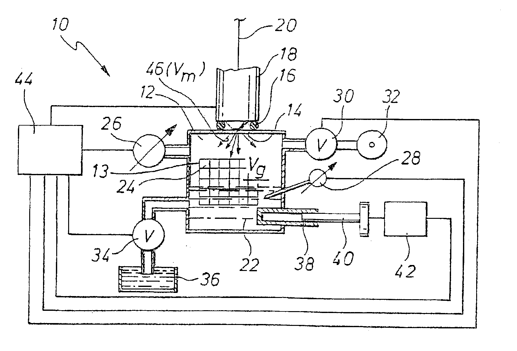
[0033]In FIG. 1, an apparatus for measuring the injection quantity of injection systems is identified overall by reference numeral 10. It includes a measurement chamber 12, which at its top has an opening 14 that is in turn provided with a sealing ring 16. An injection system, in the present case an injection nozzle 18 of an injector, is placed on this sealing ring in pressuretight and fluidtight fashion. The injection nozzle 18 communicates with a high-pressure test fluid supply 20.

[0034]The lower region, in terms of FIG. 1, of the measurement chamber 12 is filled with a test fluid 22. This is a test oil, whose physical properties are equivalent to those of fuel. The upper region, in terms of FIG. 1, of the measurement chamber 12 is filled with an ideal gas, in the present case air 24. The region of the measurement chamber 12 where the air 24 is present forms a gas volume Vg. A tie line (without a reference numeral) also branches off from the upper left-hand region of the measureme...


PUM


Abstract

For measuring the injection quantity (Vm) of injection systems (18), in particular in internal combustion engines, test fluid (22) is injected by the injection system (18) into a measurement chamber (12). To increase the precision and stability of the measurement, the volume of the measurement chamber (12) is kept constant during the injection. Moreover, a gas volume (Vg) is present in the measurement chamber (12). The injected volume (Vm) of test fluid (22) is ascertained from the pressure change (dP) in the measurement chamber (12) that occurs upon an injection of test fluid (22). The ascertainment of the injected volume (Vm) is done by means of the state equation for ideal gases.

Description

CROSS-REFERENCE TO RELATED APPLICATIONS[0001]This application is a 35 USC 371 application of PCT / DE 02 / 00777, filed on Mar. 5, 2002.BACKGROUND OF THE INVENTION[0002]1. Field of the Invention[0003]The present invention relates first to a method for measuring the injection quantity of injection systems, in particular in internal combustion engines, in which a test fluid is injected by the injection system into a measurement chamber.[0004]2. Deascription of the Prior Art[0005]One method known on the market uses an apparatus known as an EMI (injection quantity indicator). This indicator comprises a housing, in which a piston is guided. The interior of the housing and the piston define a measurement chamber. The measurement chamber has an opening against which an injection nozzle can be placed in a pressure-tight fashion. If the injection nozzle injects fuel into the measurement chamber, a fluid located in the measurement chamber is positively displaced. As a result, the piston moves, wh...

Claims


Application Information

Patent Timeline
Patent Type & Authority Patents(United States)
IPC IPC(8): F02M65/00F02D35/00F02D45/00
CPCF02M65/001
Inventor SCHOEFFEL, EBERHARDBRAUN, HANSSEIDEL, JOSEF
Owner ROBERT BOSCH GMBH
Why Eureka
Try Eureka