
Closure device for a convertible top

a technology of a closure device and a convertible top, which is applied in the direction of carpet fasteners, roofs, transportation and packaging, etc., can solve the problems of limited loading capacity of the driving cable in respect of the force transmission, described solutions are generally beset, and achieve the effect of not occupying a large amount of spa

Active Publication Date: 2005-07-12
WEBASTO EDSCHA CABRIO
View PDF9 Cites 3 Cited by
  • Summary
  • Abstract
  • Description
  • Claims
  • Application Information

AI Technical Summary

Benefits of technology

[0008]The provision of a second, drivable sliding element advantageously achieves the situation where, on the one hand, force transmission can take place during driving of the hook, which is secured in a pivotable manner on the first sliding element, and, on the other hand, the second sliding element can be optimized in respect of its low-friction guidance, while the first sliding element, which bears the closure hook, can be guided and dimensioned in respect of the closing and retaining forces which are to be applied.
[0009]In a preferred embodiment of the present invention, the first sliding element and the second sliding element are guided linearly on the roof frame in a linear guide, with the result that particularly straightforward movements and particularly straightforward structural arrangements are made possible.
[0010]A control link is particularly advantageously connected, on the one hand, in an articulated manner to the hook and, on the other hand, in an articulated manner to the second sliding element, with the result that corresponding force deflection, which makes it possible for the driven linear movement of the second sliding element to be converted into a rotary movement of the hook, can easily be realized with just a small number of components.
[0011]The second sliding element is particularly advantageously guided such that it can be moved linearly in a linear guide, the control link, over a first part of the linear movement, being retained relative to the second sliding element in a first position by means of the linear guide, and it being possible for the control link, over a second part of the linear movement, to be moved in relation to the second sliding element by means of a recess provided in the linear guide. In this way, a, in respect of the sliding elements, location-dependent activation of the rotary movement of the hook is achieved using extremely straightforward means, without additional or complex parts, for example special slot guides, having to be provided. It is possible, in principle, to provide a commercially available linear guide, formed for example as an extruded profile, for the purpose of guiding the sliding elements, it being possible for the activating means which triggers the closure operation to be designed by a simple recess in the linear guide.
[0013]Furthermore, it may particularly advantageously be provided that, in a position in which the hook is in full engagement with the hoop catch, the control link is arranged in a dead-center position or in an over-dead-center position in relation to the hook. As a result, in the case of the convertible top being subjected, from the outside, to the action of forces which ultimately subject the rotatable hook to a torque, a force which is directed essentially in the longitudinal direction of the control link is transmitted to the control link, this preventing further force transmission for example to a linear drive of the closure device. As a result, the roof frame is secured particularly reliably on the bodywork-mounted frame element.
[0014]Furthermore, a front bow of the convertible top may be secured, particularly advantageously, on the first sliding element. By virtue of rearward displacement of the first sliding element, the front bow is thus also displaced rearwardly relative to the roof frames. If the front bow is a front bow of a fully convertible top, then an essentially U-shaped region which is open to the front is produced in the front end region of the convertible top, this U-shaped region, in the case of many convertible vehicles, in particular in the case of small convertible vehicles, allowing the open convertible top to be advantageously stowed in the rear region of the vehicle since the roof frames, when they project freely in the forward direction, can be stowed to the sides of the rear passenger seats and thus do not take up a large amount of space. In the case of the front bow being designed as a front bow of a folding / sliding top, the combination of the first sliding element with the front bow provides a driven movement for the front bow and / or the entire folding / sliding top.

Problems solved by technology

A fundamental disadvantage of such driving-cable drives is the only limited loading capacity of the driving cables in respect of the force transmission.
The above described solutions are generally beset by the problem of relatively large frictional forces occurring when sliding elements are used.
Alongside additional costs and structural outlay, this solution is also unsatisfactory in that, in the case of the prior-art designs with the additional driving force, the frictional losses also increase, with the result that it is possible to achieve a less than proportional improvement in the forces which can ultimately be applied to the closure hook.

Method used


Image

  • Closure device for a convertible top
  • Closure device for a convertible top
  • Closure device for a convertible top

Examples


Embodiment Construction

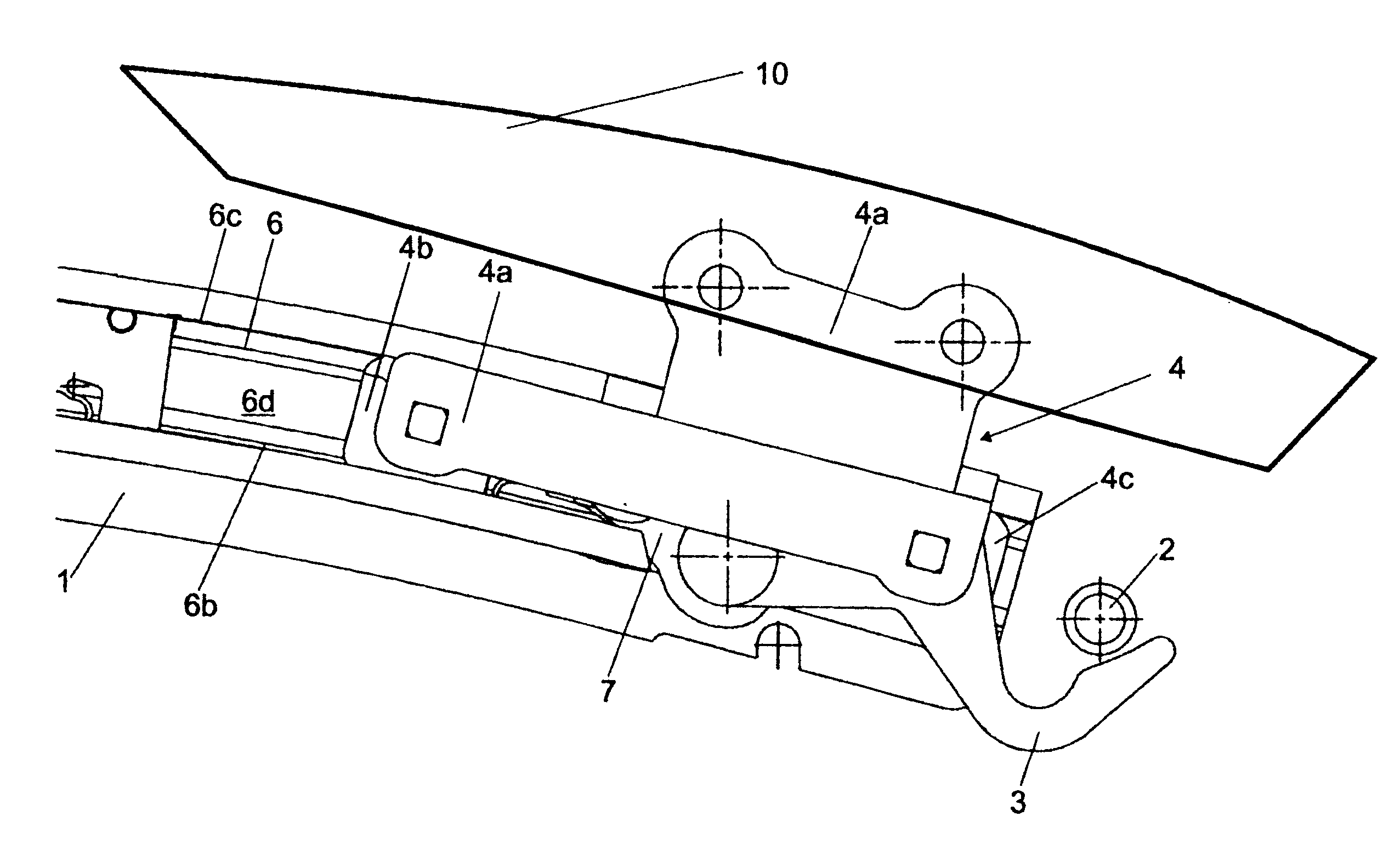
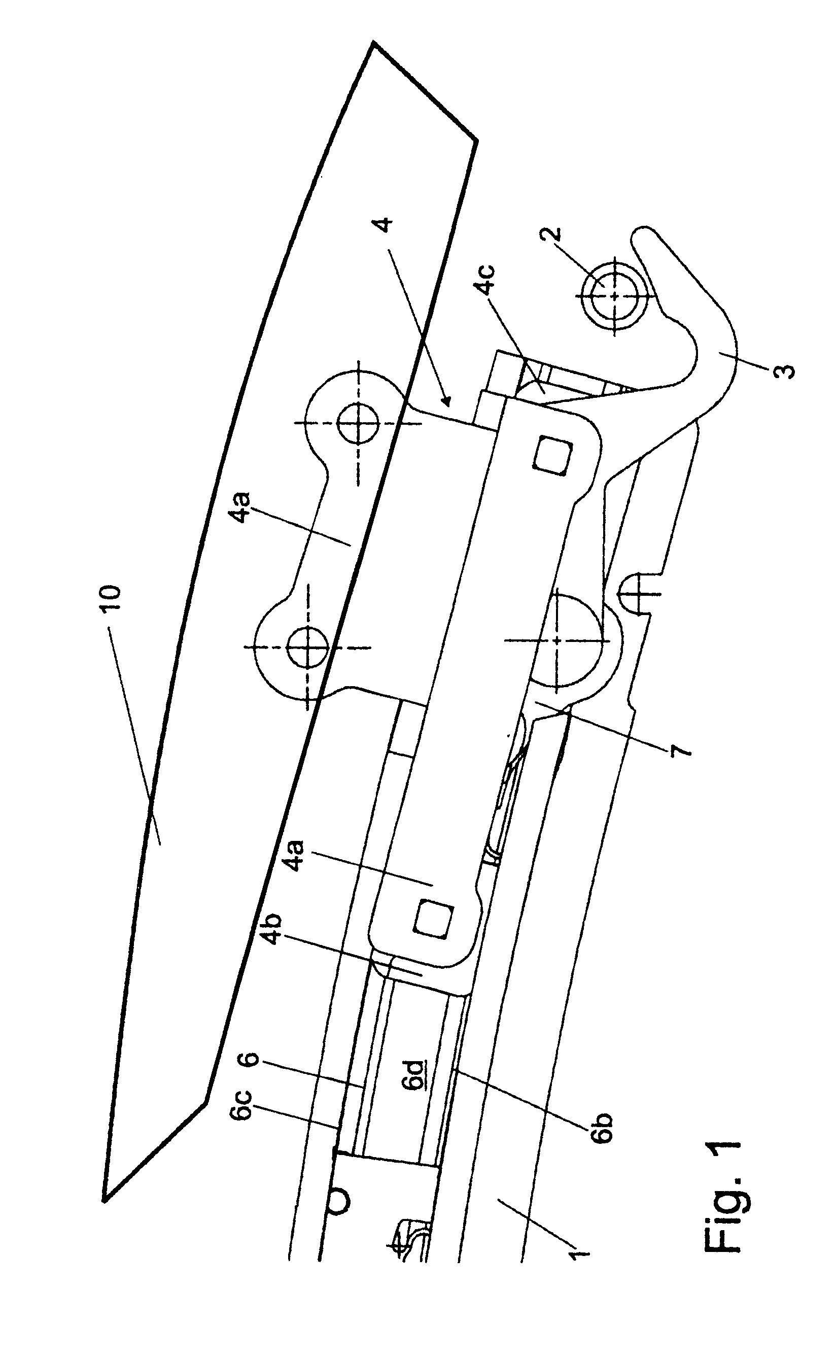
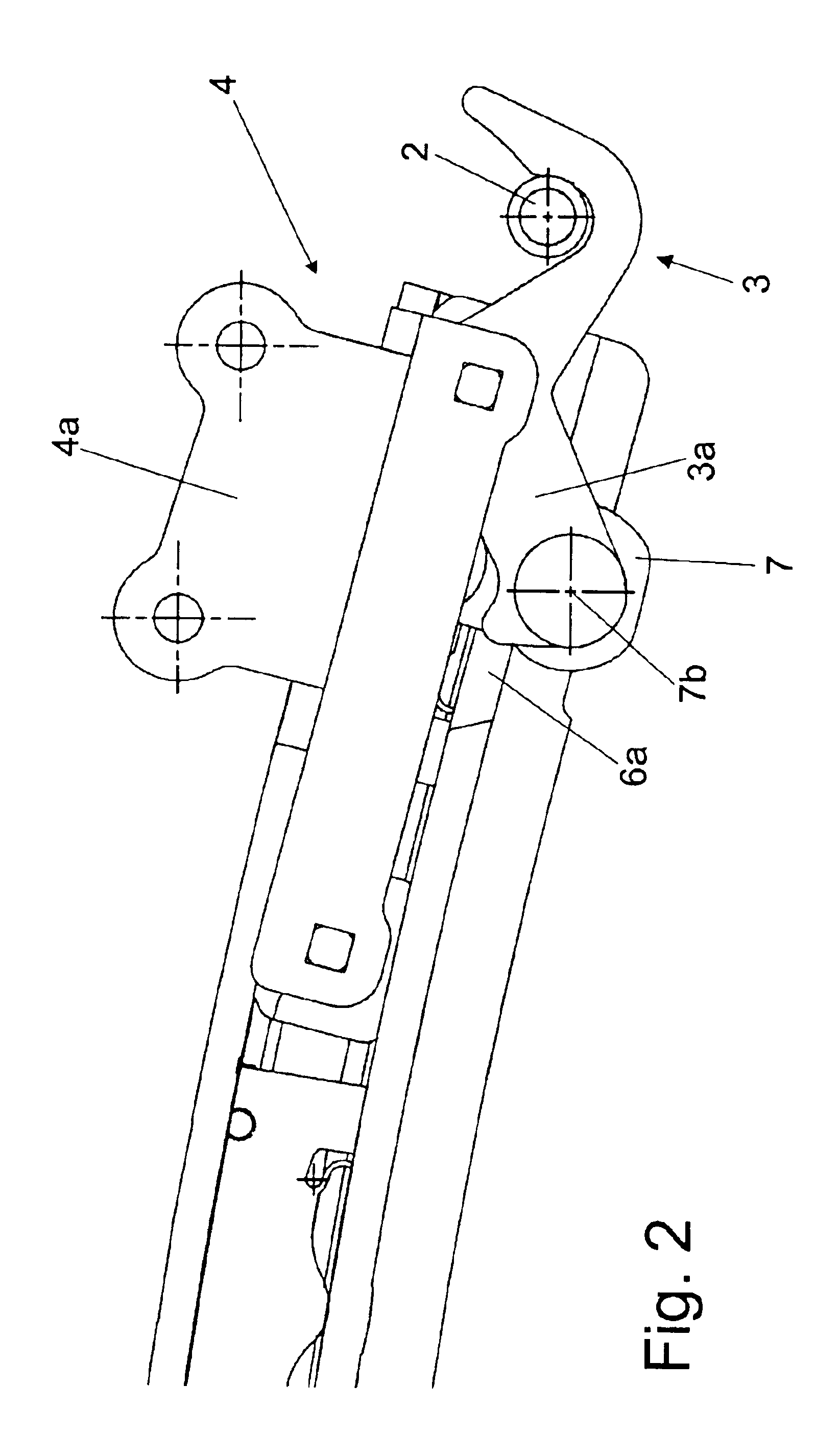
[0020]FIG. 1 shows a front end region of a lateral roof frame 1 of a convertible top, in particular of a folding / sliding top, which can be connected in a releasable manner to a frame element (not illustrated), in particular a front frame of a windshield. This allows the folding / sliding top to be removed altogether, with the result that the vehicle can be a fully convertible vehicle. A hoop catch 2 is provided on the lateral roof frame 1.

[0021]The roof frame 1 has multiple profiling, the profiling forming a linear guide 6 provided on the roof frame. A first sliding element 4 is accommodated on the linear guide 6 such that it can be displaced longitudinally along the linear guide 6. The first sliding element 4 comprises a sliding-element carrier 4a and also a first sliding block 4b and a second sliding block 4c, the sliding blocks 4b, 4c each being secured in a rotatable manner on the sliding-element carrier 4a. A hook 3 is accommodated on the sliding-element carrier 4a in a collinear...


PUM


Abstract

A closure device for a convertible top includes a lateral roof frame, a hoop element, and a pivotable hook arranged on the lateral roof frame which can be brought into engagement with the hoop element. The closure device also includes a first sliding element, the hook being accommodated in a pivotable manner on the first sliding element, and a second sliding element, it being possible for pivoting of the hook to be driven by a drivable movement of the second sliding element relative to the first sliding element.

Description

[0001]Priority is claimed to German Patent Application DE 102 42 773.9, filed on Sep. 14, 2002, the entire disclosure of which is incorporated by reference herein.BACKGROUND[0002]The present invention relates to a closure device for a convertible top, comprising a lateral roof frame, a hoop element, and a pivotable hook arranged on the lateral roof frame and which can be brought into engagement with the hoop element.[0003]Convertible-vehicle construction has provided convertible tops in which the lateral roof-frame parts can be secured on a frame element of the vehicle, in particular on a rigid windshield frame, such that they can be released by means of movable closure hooks and hoop catches which correspond with the latter and are provided on the windshield frame. In the case of convertible tops, which open and close in an automated manner, these closure devices are provided with a separate drive.[0004]Also known are folding / sliding tops in which a front end of a flexible fabric i...

Claims


Application Information

Patent Timeline
Patent Type & Authority Patents(United States)
IPC IPC(8): B60J7/185
CPCB60J7/1851Y10S292/05
Inventor OBENDIEK, KLAUSWÜLLRICH, HEINRICHHABERL, FRANZ
Owner WEBASTO EDSCHA CABRIO
Learn More