Clutch mechanism

a technology of clutch mechanism and clutch mechanism, which is applied in the direction of seating, pedestrian/occupant safety arrangement, and gearing, etc., can solve the problems of increased manufacturing cost of the clutch mechanism, complicated structure of the pneumatically actuated clutch mechanism, and inability to properly function in the ambient environment. , to achieve the effect of inhibiting the transmission of force to the force output cabl

Inactive Publication Date: 2012-10-23
TOYOTA BOSHOKU KK
View PDF6 Cites 3 Cited by
  • Summary
  • Abstract
  • Description
  • Claims
  • Application Information

AI Technical Summary

Benefits of technology

[0006]In one aspect of the present invention, a clutch mechanism for selectively transmitting a force applied thereto may include an operation bracket that is rotatably connected to the vehicle seat via a first pivot shaft and is connected to a force output cable, a rotatable arm that is rotatably connected to the operation bracket via the first pivot shaft and is connected to a force input cable, and a swing arm that is rotatably connected to the operation bracket via a second pivot shaft. The operation bracket includes a curved slot formed therein. The rotatable arm includes an elongated slot that has a toothed portion. The swing arm includes an engagement portion that movably engages both of the curved slot of the operation bracket and the elongated slot of the rotatable arm. When the force is applied quickly to the force input cable, the rotatable arm is rotated quickly about the first pivot shaft relative to the operation bracket whereas the swing arm is rotated slowly by a gravitational force about the second pivot shaft along with rotation of the rotatable arm, and as a result, the engagement portion of the swing arm engages the toothed portion of the elongated slot of the rotatable arm. Upon engagement of the engagement portion of the swing arm and the toothed portion of the rotatable arm, the rotatable arm can be rotationally locked with respect to the operation bracket, so that the operation bracket is rotated with the rotatable arm about the first pivot shaft, thereby allowing transmission of the force to the force output cable. When the force is applied slowly to the force input cable, the rotatable arm is rotated slowly about the first pivot shaft relative to the operation bracket while the swing arm is rotated slowly by the gravitational force about the second pivot shaft along with rotation of the rotatable arm, and as a result, the rotatable arm is continuously rotated relative to the operation bracket while moving the engagement portion of the swing arm along the elongated slot of the rotatable arm and the curved slot of the operation bracket. Upon continuous rotation of the rotatable arm relative to the operation bracket, the operation bracket can be prevented from being rotated about the first pivot shaft, thereby inhibiting the transmission of the force to the force output cable.
[0007]According to this aspect, when the force is applied quickly to the force input cable, the rotatable arm can be reliably rotationally locked with respect to the operation bracket (i.e., the rotatable arm can be mechanically integrated with the operation bracket), so that the operation bracket can be reliably rotated with the rotatable arm about the first pivot shaft. Therefore, when the force is applied quickly to the force input cable, the force can be reliably transmitted to the force output cable.
[0008]Also, because the swing arm is arranged and constructed to be rotated by the gravitational force about the second pivot shaft, it is not necessary to use springs or other such biasing members in order to rotate the swing arm. Therefore, the clutch mechanism may have a simplified structure. This may lead to an reduced manufacturing cost of the clutch mechanism.

Problems solved by technology

Therefore, the clutch mechanism may not properly function depending on an ambient temperature even if the force is applied quickly.
In addition, the pneumatically actuated clutch mechanism may have a complicated structure.
This may lead to an increased manufacturing cost of the clutch mechanism.

Method used


Image

  • Clutch mechanism
  • Clutch mechanism
  • Clutch mechanism

Examples


Embodiment Construction

[0019]A representative example of the present invention has been described in detail with reference to the attached drawings. This detailed description is merely intended to teach a person of skill in the art further details for practicing preferred aspects of the present invention and is not intended to limit the scope of the invention. Only the claims define the scope of the claimed invention. Therefore, combinations of features and steps disclosed in the foregoing detail description may not be necessary to practice the invention in the broadest sense, and are instead taught merely to particularly describe detailed representative examples of the invention. Moreover, the various features taught in this specification may be combined in ways that are not specifically enumerated in order to obtain additional useful embodiments of the present invention.

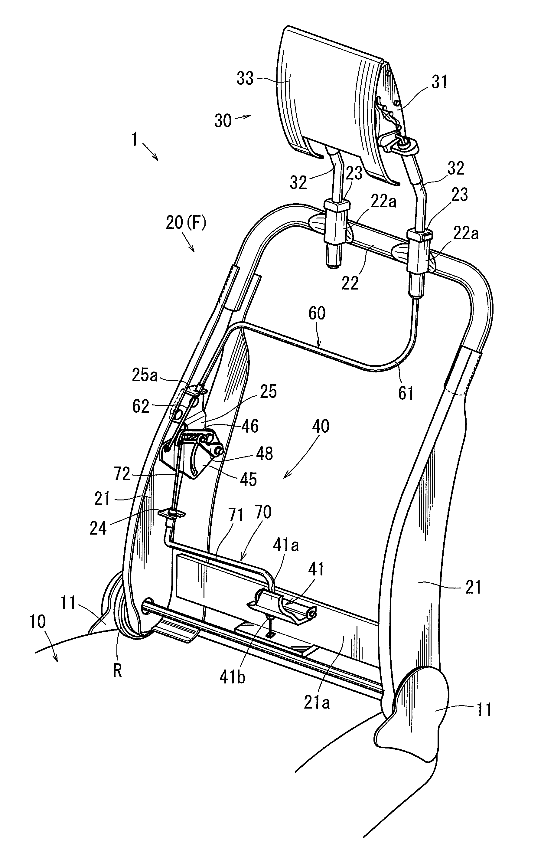
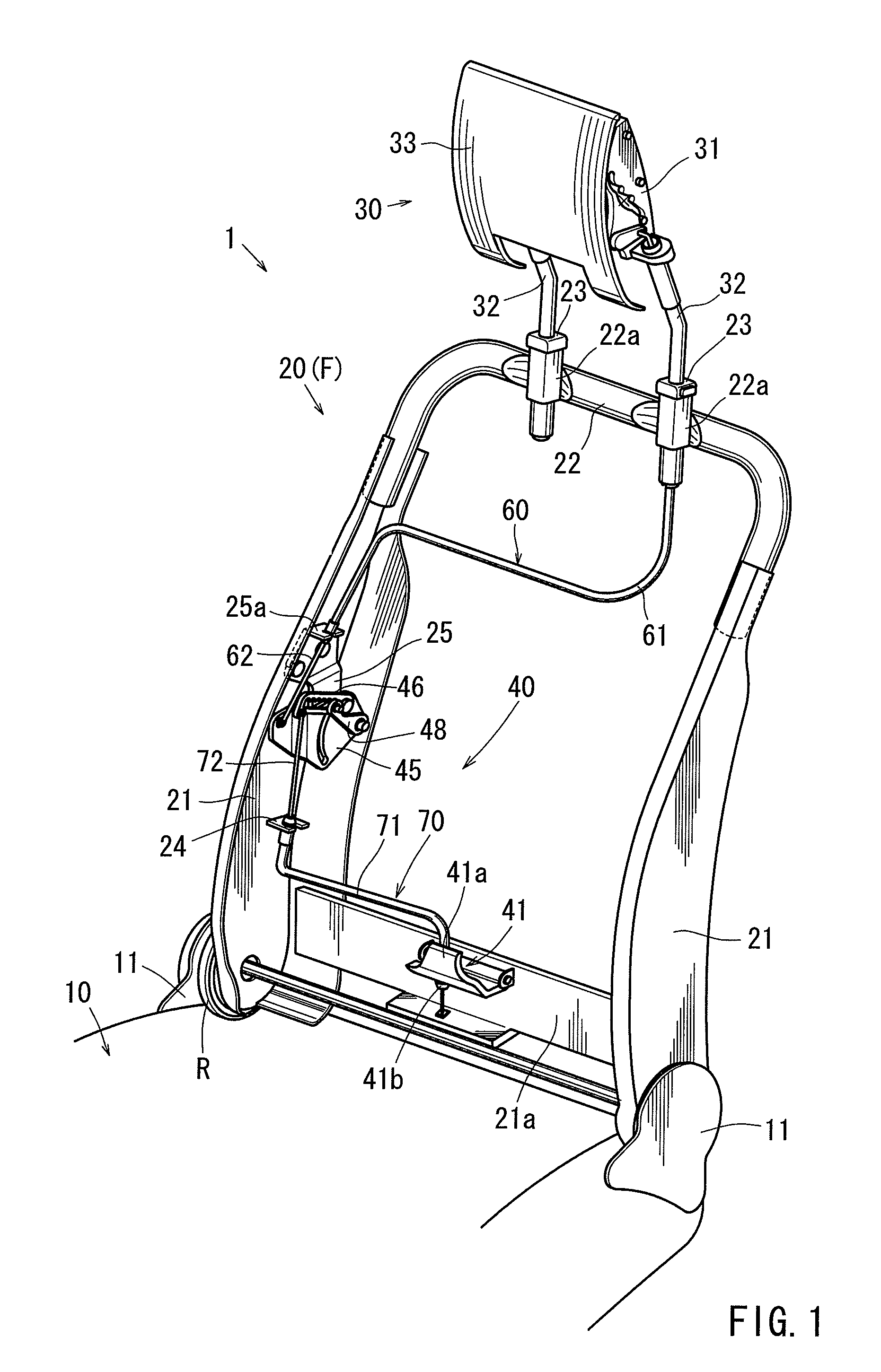
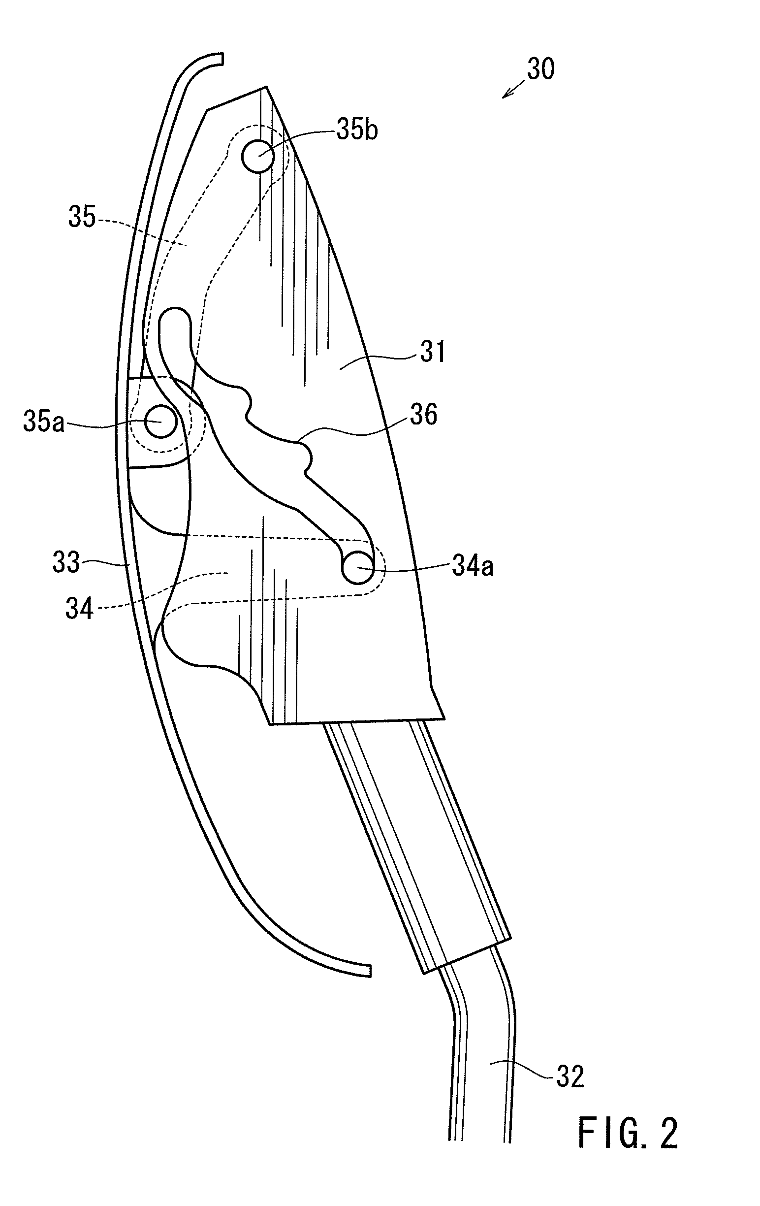
[0020]A detailed representative embodiment of the present invention is shown in FIG. 1 to FIG. 9.

[0021]As shown in FIG. 1, a representa...


PUM


Abstract

A clutch mechanism for selectively transmitting a force applied thereto may include an operation bracket that is rotatably connected to the vehicle seat via a first pivot shaft and is connected to a force output cable, a rotatable arm that is rotatably connected to the operation bracket via the first pivot shaft and is connected to a force input cable, and a swing arm that is rotatably connected to the operation bracket via a second pivot shaft. The operation bracket includes a curved slot formed therein. The rotatable arm includes an elongated slot that has a toothed portion. The swing arm includes an engagement portion that movably engages both of the curved slot of the operation bracket and the elongated slot of the rotatable arm.

Description

[0001]This application claims priority to Japanese patent application serial number 2007-301620, the contents of which are incorporated herein by reference.BACKGROUND OF THE INVENTION[0002]The present invention relates to clutch mechanisms for use in vehicle seats and force transmission mechanisms having such clutch mechanisms. More particularly, the present invention relates to clutch mechanisms that are constructed to function when external forces are applied thereto via force input cables (e.g., when seat backs of the seats are pressed rearwardly by backs of passengers sitting on the vehicle seats), thereby selectively transmitting the external forces to force output cables disposed in the seats as pulling forces, and force transmission mechanisms having such clutch mechanisms.[0003]A clutch mechanism for use in a vehicle seat that is constructed to function when an external force is applied thereto is already known. Such a clutch mechanism is taught, for example, by German Paten...

Claims


Application Information

Patent Timeline
Patent Type & Authority Patents(United States)
IPC IPC(8): A47C7/36B60N2/427
CPCB60N2/4885Y10T74/18696B60N2/888
Inventor YAMAGUCHI, TAKAOSASAKI, ATSUKI
Owner TOYOTA BOSHOKU KK
Why Eureka
Try Eureka