Vehicle exterior rearview mirror assembly

a rearview mirror and assembly technology, applied in the field of exterior rearview mirror assembly, can solve the problems of increasing fuel economy, generating noise that can be heard, and reducing fuel economy, so as to reduce wind drag and reduce nois

Inactive Publication Date: 2005-07-12
DONNELLY CORP
View PDF56 Cites 144 Cited by
  • Summary
  • Abstract
  • Description
  • Claims
  • Application Information

AI Technical Summary

Benefits of technology

[0007]In the exterior rearview mirror assembly of the present invention, the angular orientation of the movable portion of the mirror assembly is selectively adjusted towards the side of the vehicle body while the vehicle is in motion to reduce the wind drag generated by the mirror assembly, thereby, reducing the wind noise associated with the mirror assembly.
[0010]According to another form of the invention, a mirror system for a vehicle includes an exterior rearview mirror assembly and a control. The exterior rearview mirror assembly includes a reflective element, a fixed portion, which is configured to mount to a side of a vehicle, and a movable portion, which is movably mounted to the fixed portion. The reflective element is supported in the movable portion by a reflective element actuator and has a generally rearward field of view when the mirror assembly is mounted to the vehicle. The reflective element actuator provides selective adjustment of the orientation of the reflective element to adjust the rearward field of view. The mirror assembly also includes a movable portion actuator for selectively moving the movable portion between a first viewing position, wherein the movable portion is extended outwardly from the vehicle at a first angle with respect to the side of the vehicle, and a second viewing position, wherein the movable portion is extended outwardly from the vehicle at a second angle with respect to the side of the vehicle. The control selectively actuates the movable portion actuator to move the movable portion about the fixed portion to one of the viewing positions, while the reflective element actuator is adapted to be directed to a desired, preferably driver selected orientation to maintain the rearward field of view of the reflective element independent of the position of the movable portion. In this manner, a driver of the vehicle can pre-select an orientation of the reflective element, which will remain generally unchanged even when the movable portion of the mirror assembly is moved or pivoted closer toward the side of the vehicle.
[0020]As will be understood, the exterior rearview mirror system of the present invention provides a mirror assembly that creates less drag than conventional fixed mirror assembly designs to thereby reduce wind noise. In addition, the rearview mirror system maximizes the use of components already available in the mirror assembly by modifying or extending their functions to produce a reduced noise mirror assembly at relatively minimal cost increase over existing mirror assemblies.

Problems solved by technology

Most, if not all, exterior rearview mirror assemblies create to varying degrees wind drag, which generates noise that can be heard in the interior of most vehicles.
Another consequence of wind drag is decreased fuel economy which becomes more prevalent at higher speeds.
At lower speeds, the wind drag created by these fixed mirror assemblies may not be noticeable, but at elevated speeds, the noise level may be unacceptable.
However, these structures are not aesthetically pleasing to some automobile manufacturers.
Moreover, the cost of incorporating these various structures into the mirror assembly for some vehicles may be cost prohibitive.

Method used


Image

  • Vehicle exterior rearview mirror assembly
  • Vehicle exterior rearview mirror assembly
  • Vehicle exterior rearview mirror assembly

Examples


Embodiment Construction

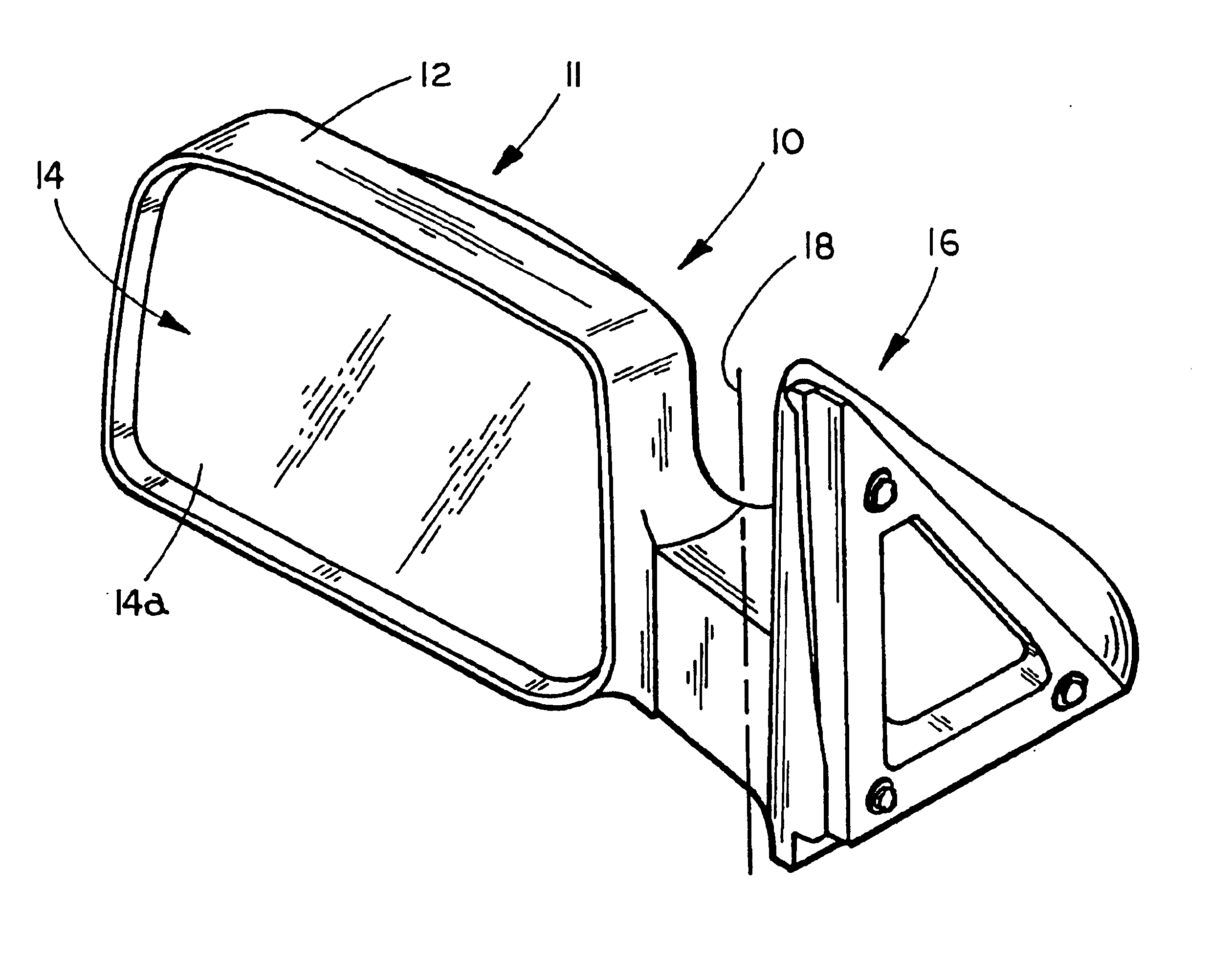
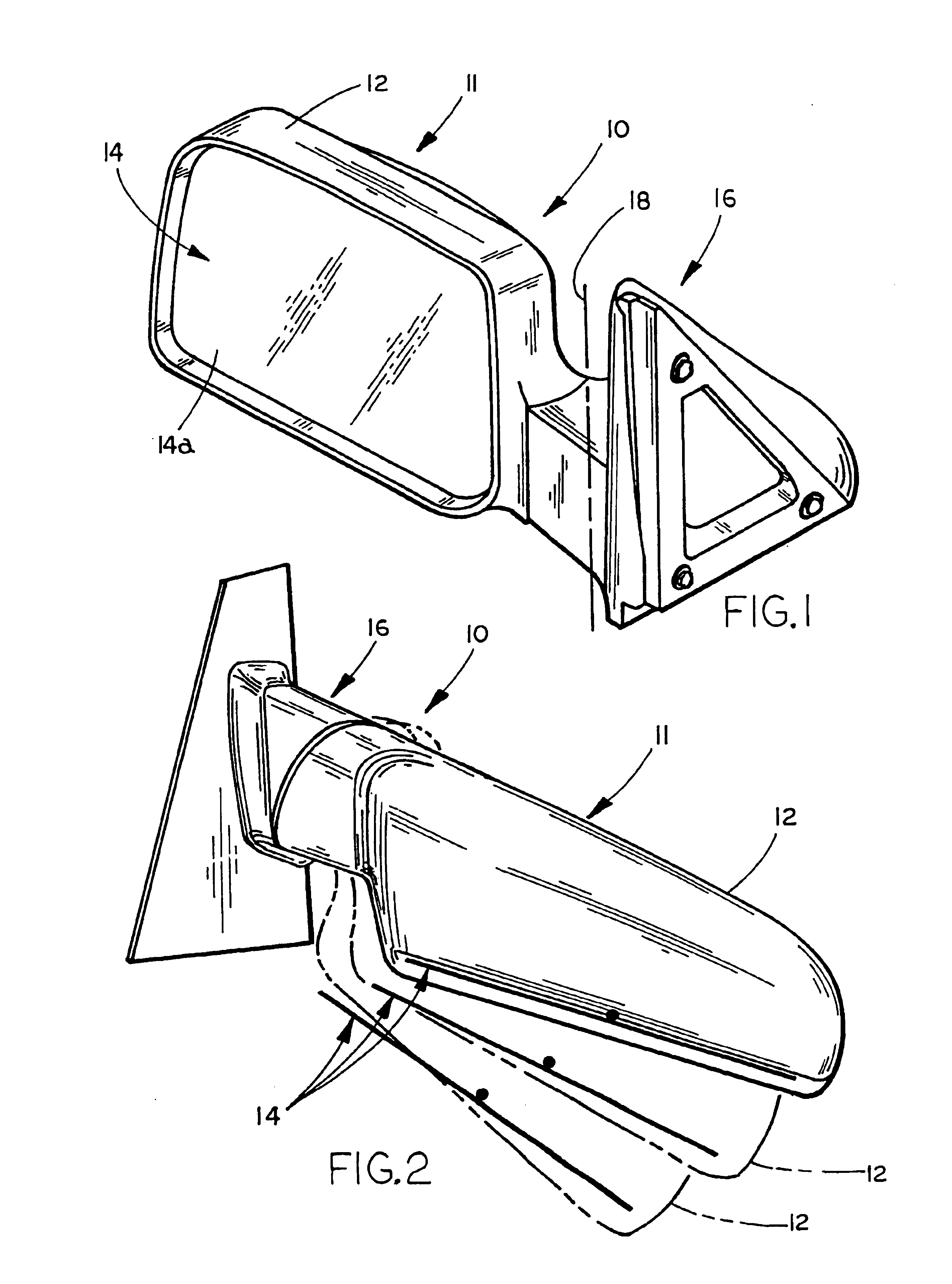
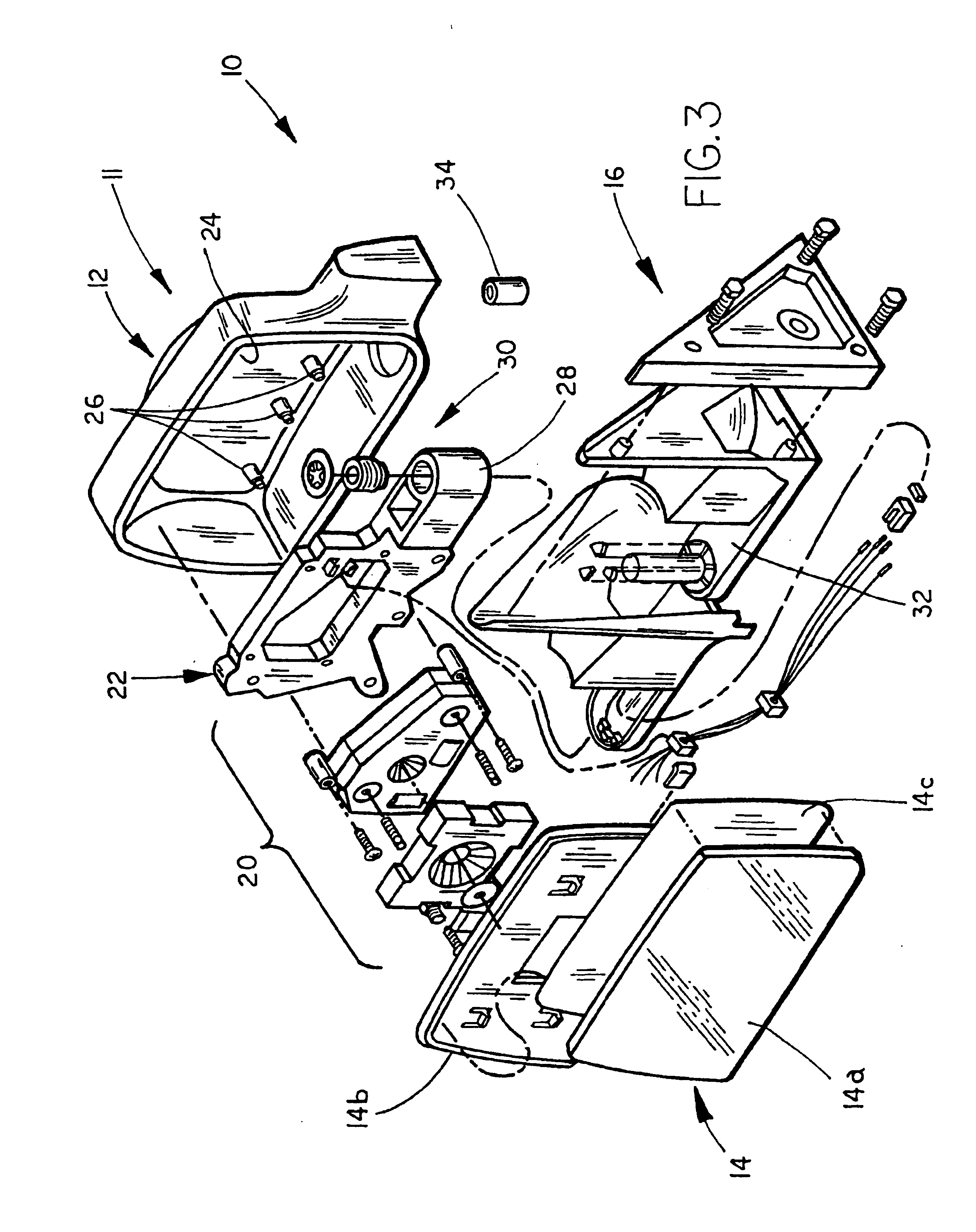
[0041]Referring to FIGS. 1 and 2, the numeral 10 generally designates a mirror system of the present invention, which includes an exterior mirror assembly 11 that is suitable for mounting to a side of a vehicle. Mirror system 10 is adapted to reduce the drag generated by air flow across exterior rearview mirror assembly 11 by varying the angular orientation of the movable portion or mirror casing of mirror assembly 11, as will be more fully described below.

[0042]As best seen in FIG. 1, exterior rearview mirror assembly 11 includes a mirror casing 12 and a reflective element assembly 14, which is housed in mirror casing 12. Casing 12 is preferably a molded housing formed from a plastic material, and, more preferably, formed from a polypropylene or glass nylon filled material. For example, casing 12 may be formed from other suitable materials, such as a polyolefin, and painted or coated with a decorative finish or provided with a skull cap, which may be painted or coated with a decora...


PUM


Abstract

A mirror system for a vehicle comprising an exterior rearview mirror assembly, which includes a fixed portion which is configured to mount to a side of the vehicle. The movable portion includes a reflective element and a reflective element actuator. The reflective element has a generally rearward field of view when the mirror system is mounted to the vehicle. The reflective element actuator provides selective adjustment of an orientation of the reflective element to adjust the rearward field of view to a desired orientation, and the movable portion is movably mounted to the fixed portion. The movable portion actuator selectively moves the movable portion between a viewing position wherein the movable portion extends outwardly from the vehicle at an angle with respect to the side of the vehicle and another viewing position wherein said movable portion extends outwardly from the vehicle at another angle with respect to the side of the vehicle. The movable portion actuator is adapted to move the movable portion to one of the positions, and the reflective element actuator is adapted to generally maintain the rearward field of view at the desired orientation independent of the position of the movable portion.

Description

[0001]This application claims priority from U.S. Provisional Application Ser. No. 60 / 301,219, filed Jun. 27, 2001, entitled VEHICLE EXTERIOR REARVIEW MIRROR ASSEMBLY, by Applicant Leo W. Pavao, and is incorporated by reference herein in its entirety.TECHNICAL FIELD AND BACKGROUND OF THE INVENTION[0002]The present invention generally relates to an exterior rearview mirror assembly and, more particularly, to an exterior rearview mirror assembly that generates reduced wind noise.[0003]Most, if not all, exterior rearview mirror assemblies create to varying degrees wind drag, which generates noise that can be heard in the interior of most vehicles. The threshold at which the noise becomes noticeable varies with the aerodynamic properties of the exterior of the mirror assembly, the speed of the vehicle on which the mirror assembly is mounted, and the insulation of the vehicle body. Another consequence of wind drag is decreased fuel economy which becomes more prevalent at higher speeds.[00...

Claims


Application Information

Patent Timeline
Patent Type & Authority Patents(United States)
IPC IPC(8): B60R1/02B60R1/12B60R1/062B60R1/07B60Q1/26
CPCB60Q1/2665B60R1/025B60R1/07B60R1/1207
Inventor PAVAO, LEO W.
Owner DONNELLY CORP
Why Eureka
Try Eureka