Guiding grid of variable geometry and turbocharger

Active Publication Date: 2005-07-12
BORGWARNER INC
View PDF1 Cites 42 Cited by
  • Summary
  • Abstract
  • Description
  • Claims
  • Application Information

AI Technical Summary

Benefits of technology

[0010]The invention also relates to a turbocharger having a guiding grid which comprises a turbine housing and a bearing housing that is releasably attached to the turbine housing and supports the turbine shaft. When mounting the guiding grid, the fact that the bearing housing being releasably attached to the turbine housing allows easy access to the interior of the turbine housing and to a wall surrounding the central opening

Problems solved by technology

U.S. Pat. No. 5,146,752, in particular, illustrates how laborious it is to mount the individual parts of the guiding grid in the housing, since various parts have to be matched, patch

Method used


Image

  • Guiding grid of variable geometry and turbocharger
  • Guiding grid of variable geometry and turbocharger
  • Guiding grid of variable geometry and turbocharger

Examples


Embodiment Construction

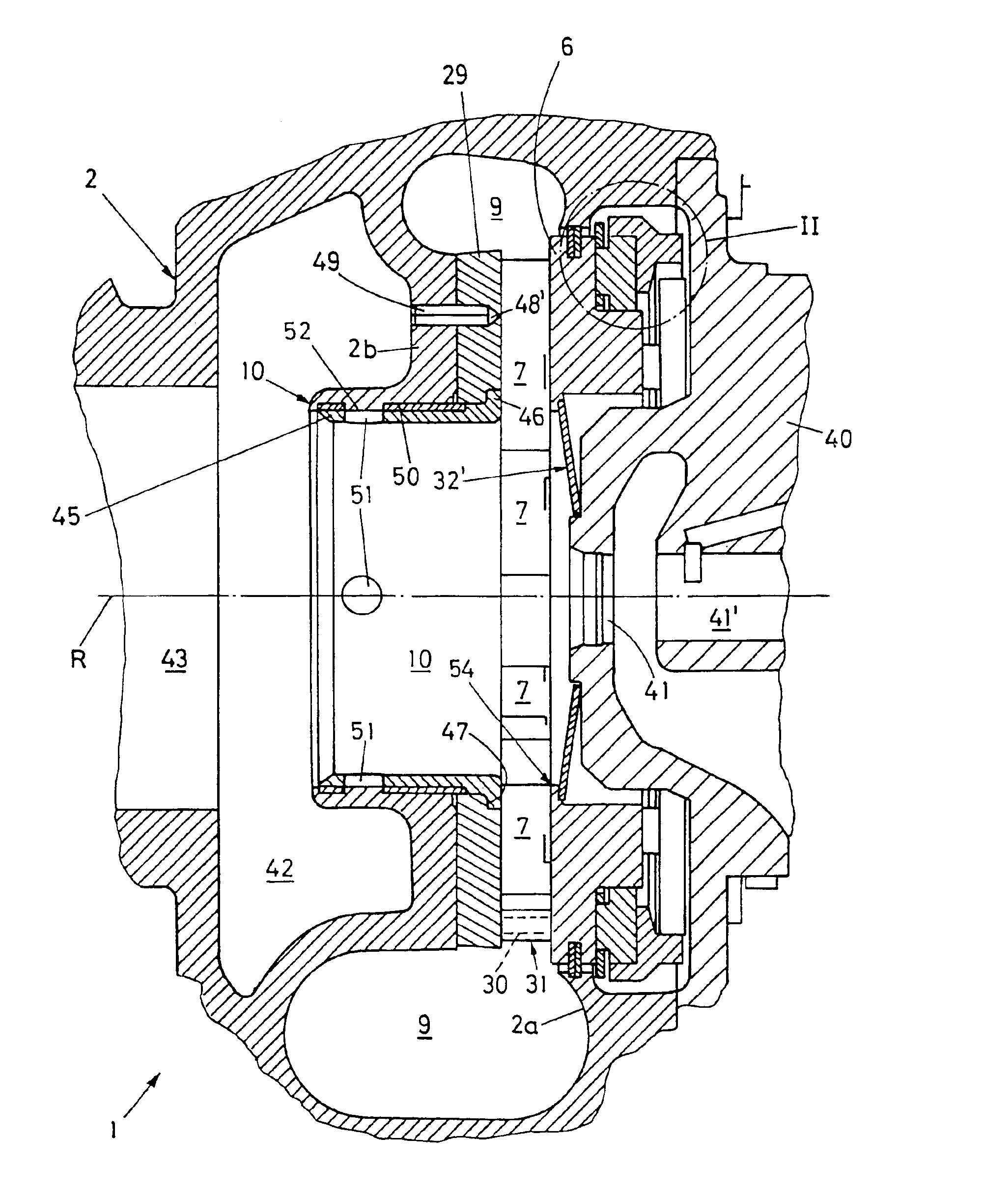
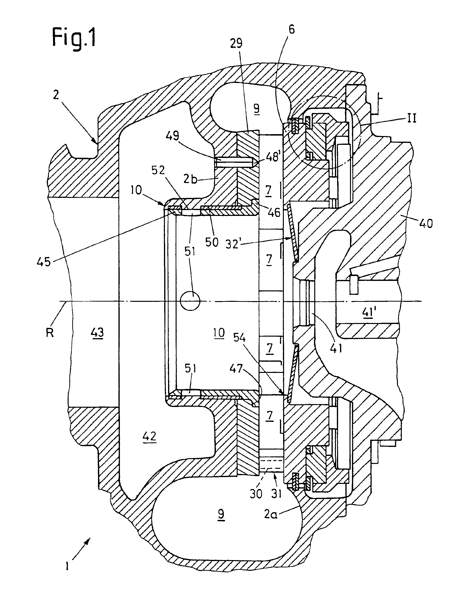
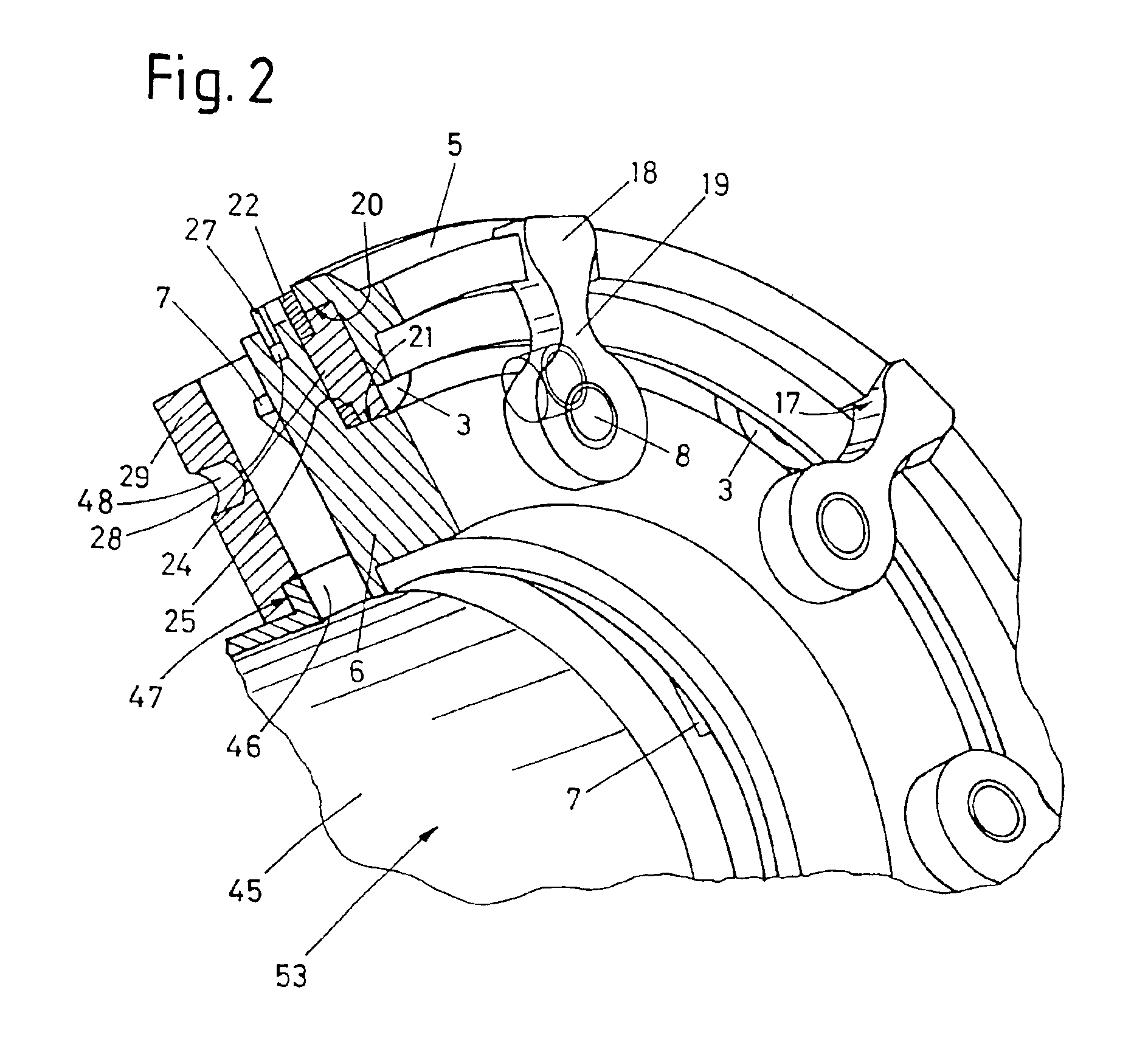
[0014]In FIG. 1, a part of a turbine housing 2 of a turbocharger 1 is represented which, typically, comprises a peripheral supply channel 9 for a fluid spirally wound around a central axis R, the fluid being of any nature, even liquid, but in case of a turbocharger supplying exhaust gas of a combustion motor as is known (not shown). This fluid is then supplied in radial direction through a plurality of guiding vanes 7 arranged around the central axis R to a turbine rotor (not shown) rotating about the central axis R. This turbine rotor is mounted, as is known, at the end of a rotor shaft (also not shown) which is supported in bearings 41 and 41′ situated within a bearing housing 40 that is releasably attached to the turbine housing 2 and fastened to it by bolts not shown. In the case of a turbocharger, this shaft extends through this bearing housing 40 to a compressor rotor located within a compressor housing that is either releasably attached to the bearing housing or may be integr...


PUM


Abstract

A guiding grid of variable geometry comprises a plurality of guiding vanes in a housing in angular distances around a central axis in an axially extending vane space of a predetermined axial distance. Each vane is pivotal about an associated pivoting axis to assume different angles in relation to the central axis and, thus, to form a nozzle of variable cross-section between each pair of adjacent vanes. A nozzle ring supports the vanes around the central axis and forms a first axial limitation of the vane space. A unison ring is displaceable relative to the nozzle ring and is connected to the vanes to pivot them. An annular disk is fixed to the housing and faces the nozzle ring in an axial distance to form a second axial limitation of the vane space and a central opening. Into this opening, a sleeve may be inserted. A fixing arrangement determines the axial position of the annular disk with respect to the housing.

Description

CROSS REFERENCE TO RELATED APPLICATION[0001]This application is based upon European Patent Application No. 02 020 412,9, filed Sep. 10, 2002, from which priority is claimed.FIELD OF THE INVENTION[0002]The present invention relates to a guiding grid or actuator of variable geometry, particularly for a turbine housing having a central outlet pipe. More particularly, the invention relates to a guiding grid which comprises a plurality of guiding vanes arranged in angular distances about a central axis in an axially extending vane space of a predetermined axial distance, each vane being pivotal about an associated pivoting axis to assume different angles in relation to the central axis and, thus, to form a nozzle of variable cross-section between each pair of adjacent vanes. A generally annular nozzle ring for supporting the plurality of pivoting vanes around the central axis forms a first axial limitation of the vane space. A displaceable unison ring is placed around the central axis re...

Claims


Application Information

Patent Timeline
IPC IPC(8): F01D17/16F01D17/00F02B37/24
CPCF01D17/165F05D2220/40
Inventor BOENING, RALF
Owner BORGWARNER INC
Why Eureka
Try Eureka