Hypodermic needle guard

a technology of hypodermic needles and guards, applied in the direction of guide needles, catheters, infusion needles, etc., can solve the problems of increasing the risk of puncture, increasing the possibility of puncture, and complicated, and achieve the effect of convenient manufactur

Inactive Publication Date: 2005-07-12
ARROW INT INC
View PDF26 Cites 93 Cited by
  • Summary
  • Abstract
  • Description
  • Claims
  • Application Information

AI Technical Summary

Benefits of technology

[0011]The present invention is directed to an apparatus that satisfies the need for a needle guard that is easy to manufacture and tha

Problems solved by technology

This action usually requires the operator to move the hand which holds the sheath toward the pointed tip of the needle, and any inaccuracy in this operation raises the possibility of a puncture.
The risk of this is greatly increased if the operator is working under stress, such as time pressure or fatigue, or is handicapped by marginal eyesight or unste

Method used


Image

  • Hypodermic needle guard
  • Hypodermic needle guard
  • Hypodermic needle guard

Examples


Embodiment Construction

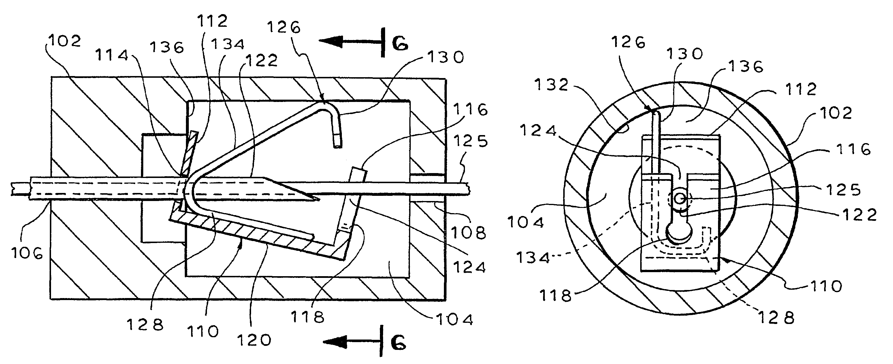
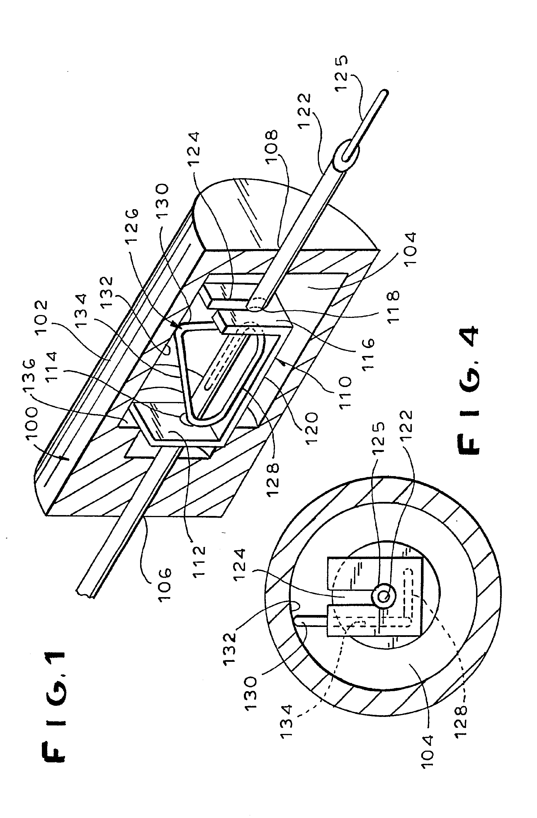
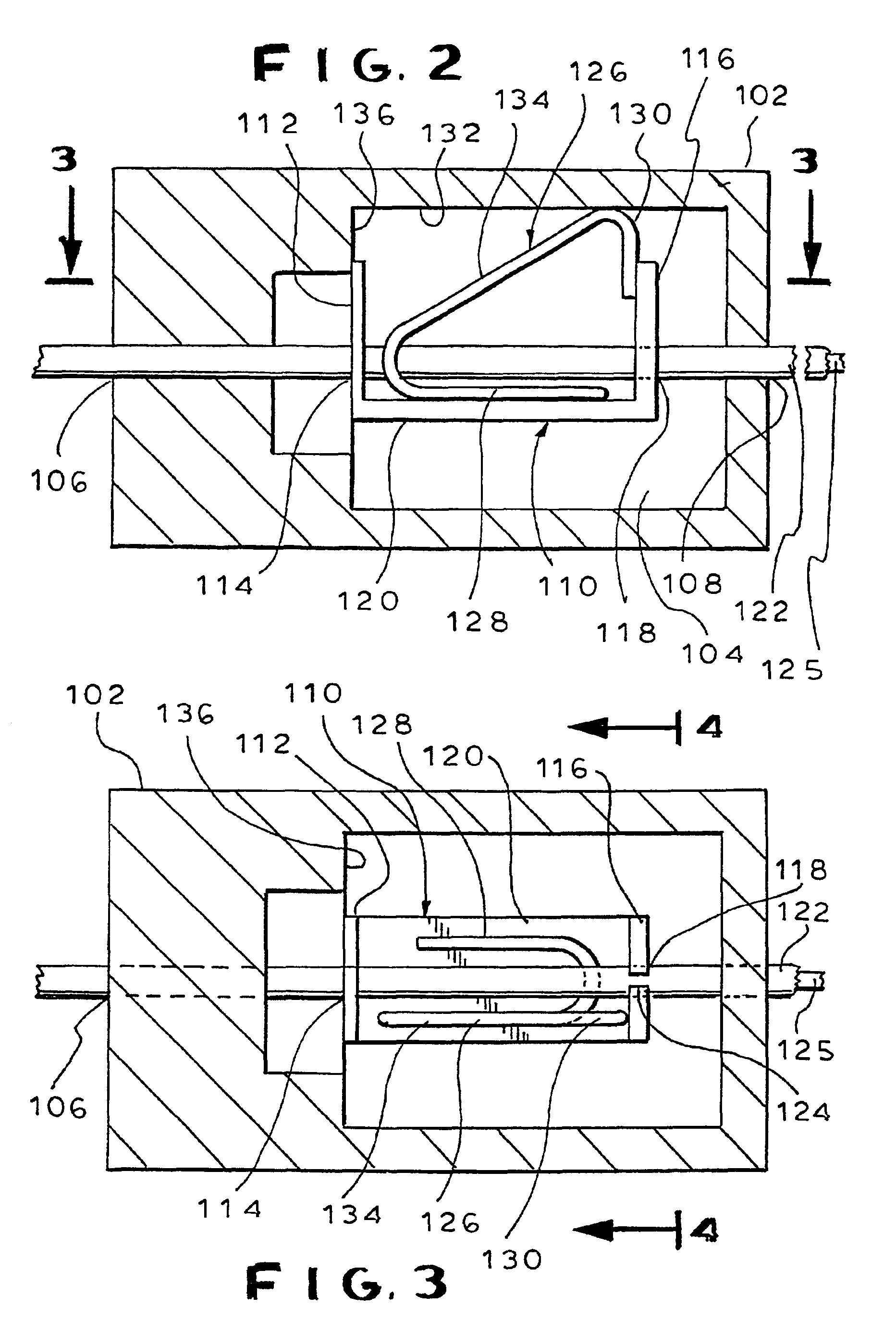
[0037]FIGS. 1 through 6 show drawings of an embodiment of a needle guard device, generally designated 100, that has features of the present invention. A housing 102 of the needle guard device 100 has an interior cavity 104 defined therein. The housing 102 is formed with a proximal opening 106 at a proximal end thereof and a distal opening 108 at a distal end thereof.

[0038]A pivoting member, generally designated 110, is located within the interior cavity 104 of the housing 102. The pivoting member 110 has a proximal wall 112 that defines a proximal opening 114. The pivoting member 110 further comprises a distal wall 116 that defines a distal opening 118. The proximal and distal walls 112 and 116 are perpendicularly attached to a base 120 to form a U-shaped pivoting member 110. The pivoting member 110 is preferably formed from a hard metal material, like steel.

[0039]The openings 114 and 118 of the pivoting member 110 are sized to allow a needle 122 to pass therethrough. More specifica...


PUM


Abstract

A device for inhibiting unintentional contact with the tip of a needle that has a wire guide disposed in a lumen thereof. A housing of the device has an interior cavity. A portion of the needle extends through the cavity and a tip of the needle is located outside of the housing during use of the needle. A pivoting member is located within the cavity and defines a distal opening and a proximal opening which are sized to allow the needle to pass through the openings. When the needle tip is within the cavity and the needle is withdrawn from the distal opening of the pivoting member, a spring or a compressible member cants the pivoting member into locking engagement with the needle to prevent further movement of the needle. Alternatively, a spring is in locking engagement with the needle to prevent its further movement. When the pivoting member is canted about the needle, a slot of the pivoting member is generally aligned with the tip of the needle so that the wire guide can extend through the slot while further forward movement of the needle through the slot is prevented.

Description

CROSS REFERENCE TO RELATED APPLICATIONS[0001]This application is a divisional of application Ser. No. 09 / 369,866 entitled HYPODERMIC NEEDLE GUARD, filed on Aug. 9, 1999, by William J. Voitasek, which was issued on Aug. 28, 2001, as U.S. Pat. No. 6,280,419. The present application is related to application Ser. No. 09 / 878,012 entitled HYPODERMIC NEEDLE GUARD, filed on Jun. 8, 2001, by William J. Voitasek, which was issued on Nov. 26, 2002, as U.S. Pat. No. 6,485,468.FIELD OF THE INVENTION[0002]This invention relates generally to insuring the safe disposal of hypodermic needles. In particular, this invention relates to a device that is storable on the needle and that automatically locks over the end of the needle when the tip of the needle has been retracted within the interior of the device.BACKGROUND OF THE INVENTION[0003]The danger of infection from accidental contact with the tip of a used hypodermic needle has long been recognized and is well documented. In most procedures, the g...

Claims


Application Information

Patent Timeline
IPC IPC(8): A61M25/06A61M5/32A61M5/31
CPCA61M25/0618A61M5/3273A61M2005/325
Inventor VOJTASEK, WILLIAM J.
Owner ARROW INT INC
Why Eureka
Try Eureka