Discharged fuel diluter and discharged fuel dilution-type fuel cell system

Inactive Publication Date: 2005-07-12
HONDA MOTOR CO LTD
View PDF2 Cites 30 Cited by
  • Summary
  • Abstract
  • Description
  • Claims
  • Application Information

AI Technical Summary

Benefits of technology

[0018]In this discharged fuel diluter, if the fuel is a gas that is lighter than air, such as hydrogen, the fuel discharged from the fuel cell enters the retention region and stays there, and thereafter spreads within the whole retention region from top to bottom, and finally flows into the dilution region located below the retention region. Especially, if the communicating portion is formed by a porous plate such as ceramics, the

Problems solved by technology

Therefore, it is necessary to discharge the accumulated N2.(2) Since condensed dewdrops of supplied water or produced water pools and causes flooding within the fuel cell, the output of the fuel cell lowers.
However, if there is an open fire or naked flame on a road, an i

Method used


Image

  • Discharged fuel diluter and discharged fuel dilution-type fuel cell system
  • Discharged fuel diluter and discharged fuel dilution-type fuel cell system
  • Discharged fuel diluter and discharged fuel dilution-type fuel cell system

Examples


Embodiment Construction

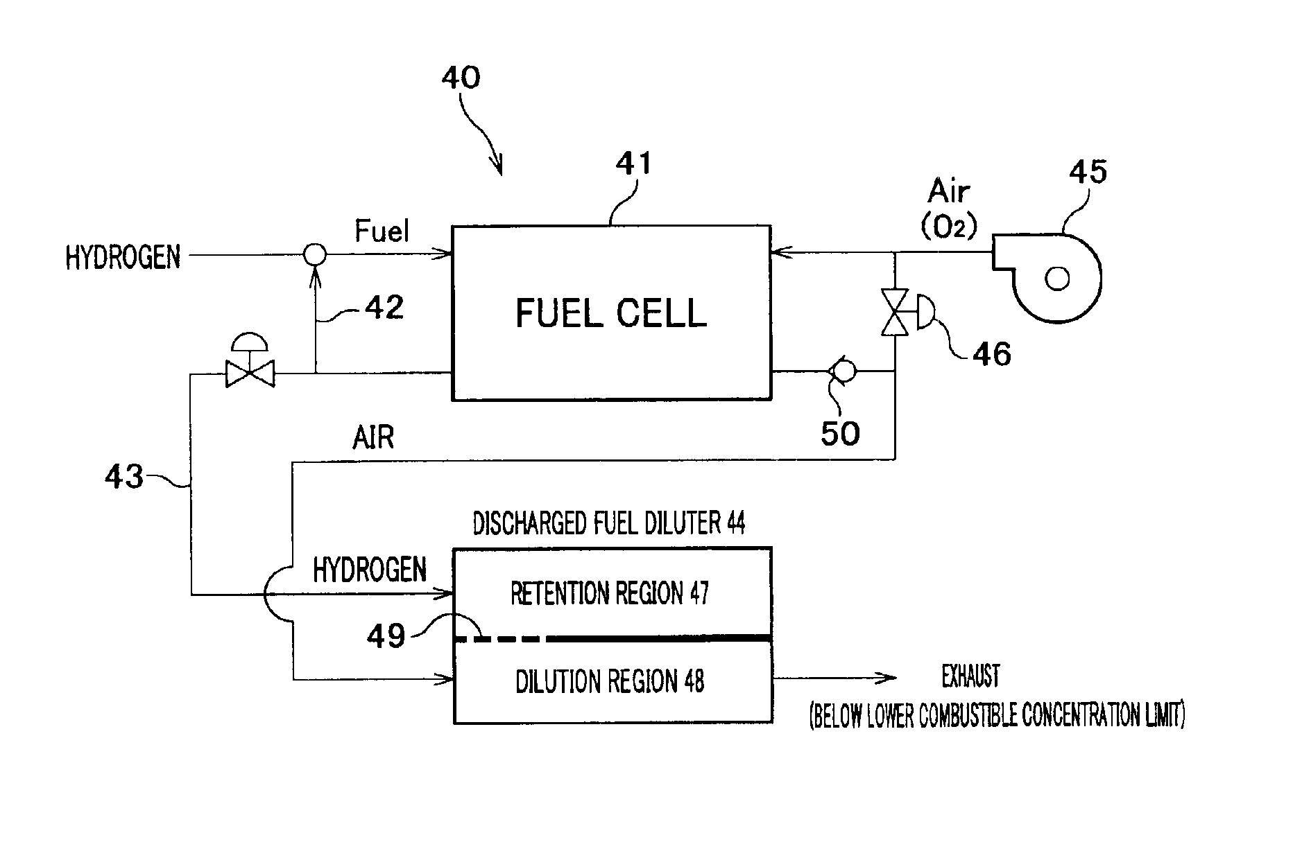
[0049]With reference to the accompanying drawings, one preferred embodiment of a discharged fuel diluter according to the invention will be described.

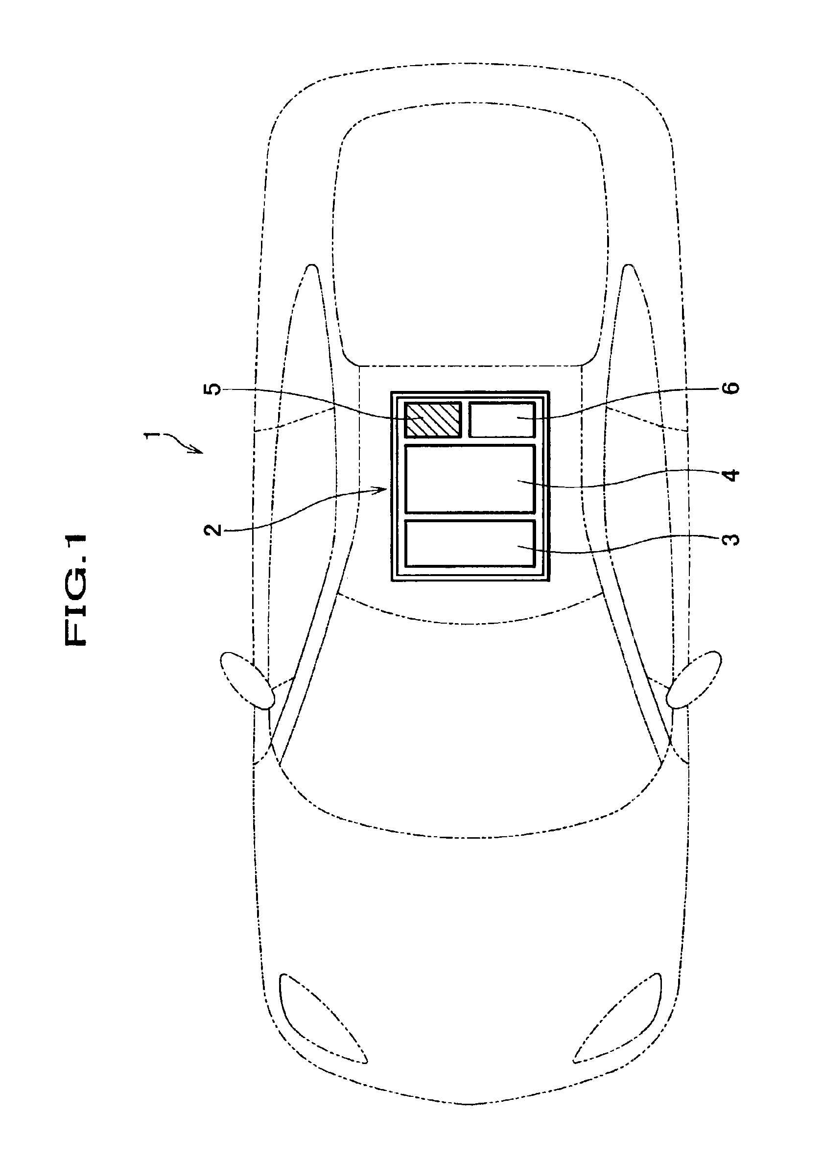
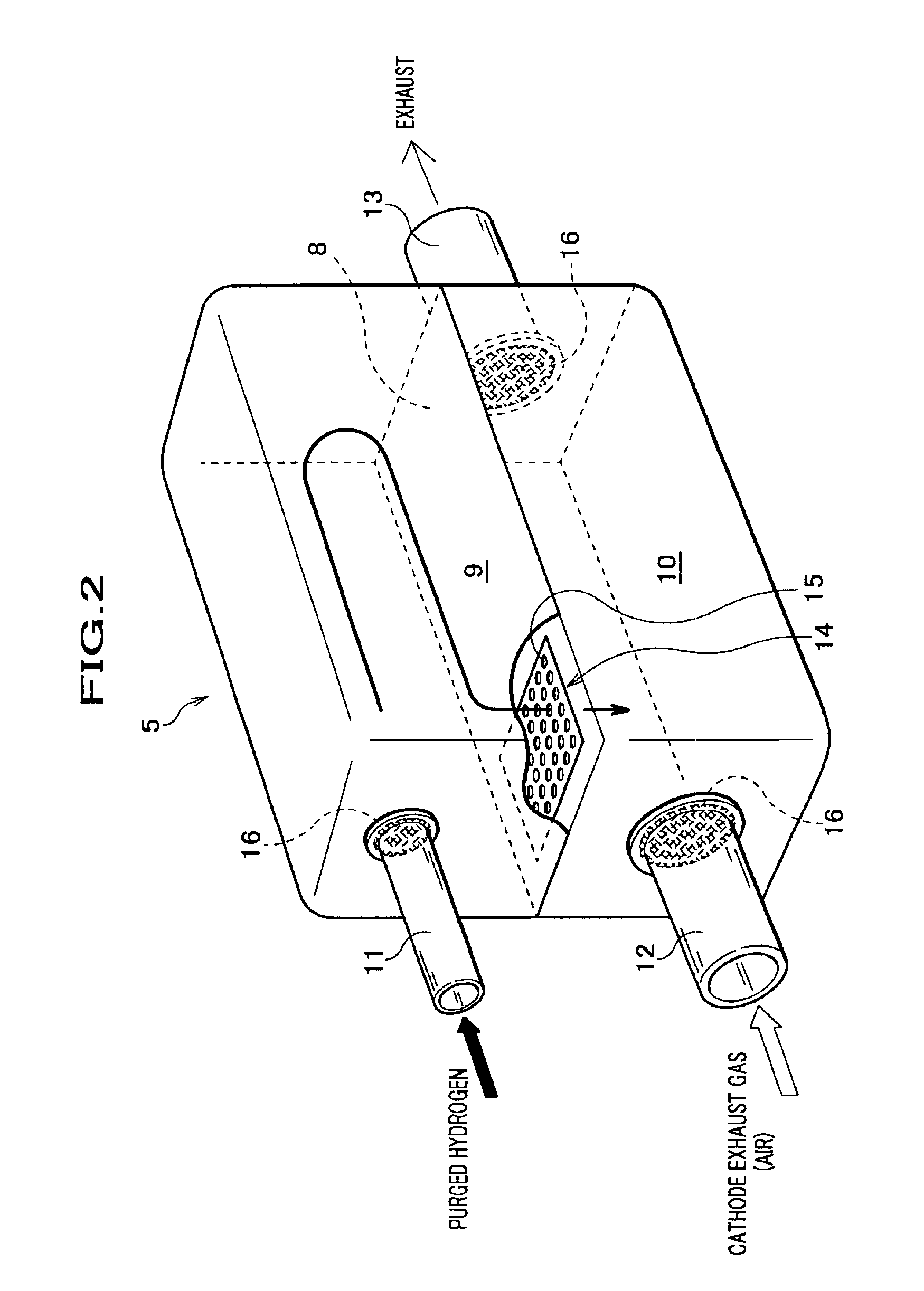
[0050]As a drawing to be referred, FIG. 1 is a view of a fuel cell-mounted electric vehicle illustrating the layout of a fuel cell system box including a discharged fuel diluter according to the invention.

[0051]As seen in FIG. 1, a fuel cell system box 2 is mounted on a fuel cell-mounted electric vehicle (hereinafter referred to as a vehicle) 1 at a center of and under the floor of the vehicle 1. In the fuel cell system box 2, a temperature regulation means 3, a fuel cell 4, a discharged fuel diluter 5, and a humidifying means 6 are located in the order from the front to the rear of the vehicle 1. However, the discharged fuel diluter 5 and the humidifying means 6 are located parallelly. The fuel cell system also comprises a non-illustrated radiator, a non-illustrated high pressure hydrogen storage tank, etc.

[0052]The fuel cell 4 genera...


PUM


Abstract

A discharged fuel diluter includes: a retention region with a predetermined volume, into which a fuel discharged from a fuel cell is retained at the time of purging; a dilution region with a predetermined volume, through which air discharged from the fuel cell flows and at which the air is mixed with the fuel from the retention region to dilute the fuel; and a communicating portion, through which the fuel flows from the retention region to the dilution region.

Description

FIELD OF THE INVENTION[0001]The present invention relates to a discharged fuel diluter and a discharged fuel dilution-type fuel cell system, and more particularly to a discharged fuel diluter and a discharged fuel dilution-type fuel cell system, wherein hydrogen as a power source for an electric vehicle is processed during the purging operation of a fuel cell mounted on the electric vehicle.BACKGROUND OF THE INVENTION[0002]In the case that a fuel cell utilizes pure hydrogen (hereinafter referred to as hydrogen) as a power source of an electric vehicle (hereinafter referred to as a vehicle), hydrogen is supplied to the fuel cell in a hydrogen circulation system in order to improve the utilization efficiency (fuel economy). In this circulation system, an ejector for absorbing hydrogen while generating negative pressure, or a hydrogen pump is employed. Both ejector and hydrogen pump require purging. Herein, the term “purging” means to temporally discharge hydrogen in the circulation sy...

Claims


Application Information

Patent Timeline
IPC IPC(8): H01M8/06B60K1/04H01M8/00H01M8/04
CPCH01M8/0662Y02E60/50
Inventor YAMAMOTO, AKIOAOYAGI, SATOSHIOGURA, MASAMIMURAKAMI, YOSHIKAZUFUKUMA, KAZUNORIKOYAMA, TAKATSUGU
Owner HONDA MOTOR CO LTD
Why Eureka
Try Eureka