Damping resistor boost writer architecture

a writer architecture and resistor technology, applied in the field of magnetic storage mediums, can solve the problems of affecting the density of bit encoding by the write circuit in comparison to the desired goal, affecting the placement of transition and bit cell size, and reducing the placement accuracy of bit encoding

Active Publication Date: 2005-07-12
TEXAS INSTR INC
View PDF2 Cites 24 Cited by
  • Summary
  • Abstract
  • Description
  • Claims
  • Application Information

AI Technical Summary

Benefits of technology

[0006]The present invention achieves technical advantages as an apparatus and method for driving a write current for an inductive head element in a magnetic storage medium, such as a hard disk drive, including an H-bridge type circuit which is capable of driving a current through the inductive head element and a boost circuit which is coupled with the H-bridge and which is operable for delivering another current during a predetermined period to the head element, wherein a sum of the currents provides the write current for the head element of the hard disk drive. Further, a resistive element is selectively coupled with the head element for providing impedance matching in which the resistive element is decoupled from the head element during delivery of the current from the boost circuit.

Problems solved by technology

Due to the inductive nature of a write circuit head and the output capacitances associated with the write circuitry, ringing effects occur in the write current signal which tend to delay the settling of the write current to its final DC value.
These ringing effects adversely affect both transition placement and bit cell size concerns.
While the accuracy of transition placement within bit cells in such a system will not be negatively affected by the ringing of the write current, the density of bit encoding by the write circuit is poor in comparison to desired goals.
This approach maintains acceptable encoding density but results in decreased placement accuracy of bit encoding and hinders subsequent recovery of data from the disk.
More particularly, if the write current has not fully settled from a prior transition, switching for the next transition might commence at totally different, uncontrolled, current levels, which results in sporadic placement of transitions in bit cells.
Therefore, both options entail undesirable performance trade-offs where ringing effects are present.
Unfortunately, since some of the write current is diverted through the damping resistor, write current through the head inductor is reduced which operates to slow down the rise and fall time of write current transitions.
While resistive damping does reduce the ringing effects, the slower rise times may not be acceptable for high performance write circuits.

Method used


Image

  • Damping resistor boost writer architecture
  • Damping resistor boost writer architecture
  • Damping resistor boost writer architecture

Examples


Embodiment Construction

[0012]The numerous innovative teachings of the present application will be described with particular reference to the presently preferred exemplary embodiments. However, it should be understood that this class of embodiments provides only a few examples of the many advantageous uses and innovative teachings herein. In general, statements made in the specification of the present application do not necessarily delimit any of the various claimed inventions. Moreover, some statements may apply to some inventive features, but not to others. Throughout the drawings, it is noted that the same reference numerals or letters will be used to designate like or equivalent elements having the same function. Detailed descriptions of known functions and constructions unnecessarily obscuring the subject matter of the present invention have been omitted for clarity.

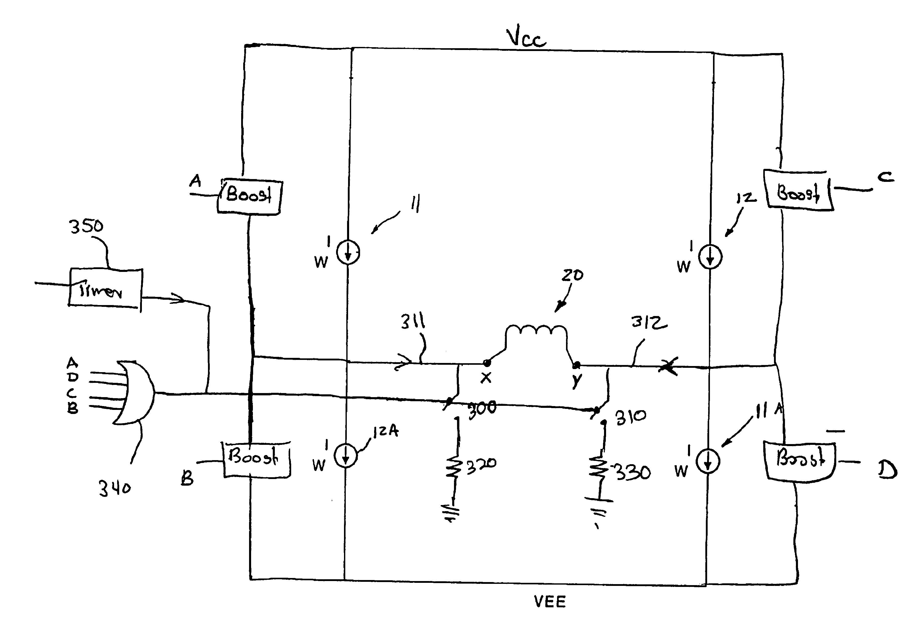
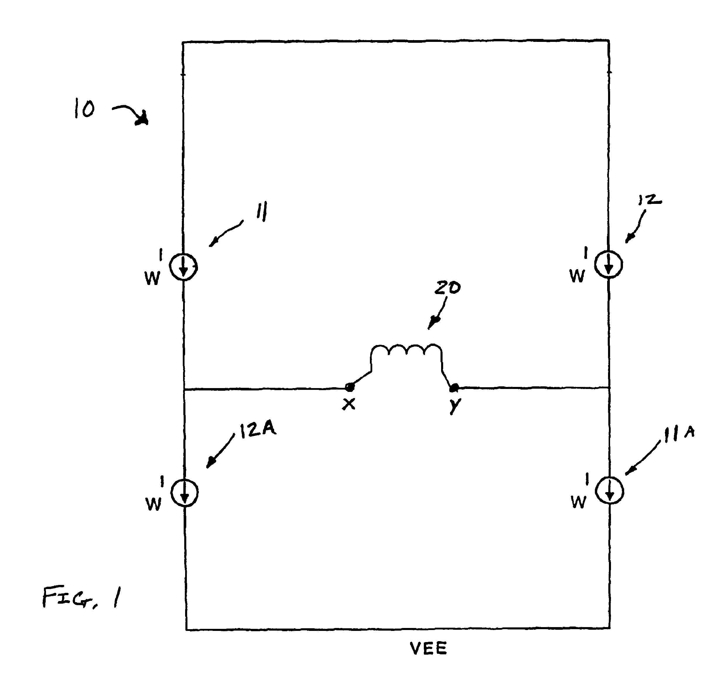
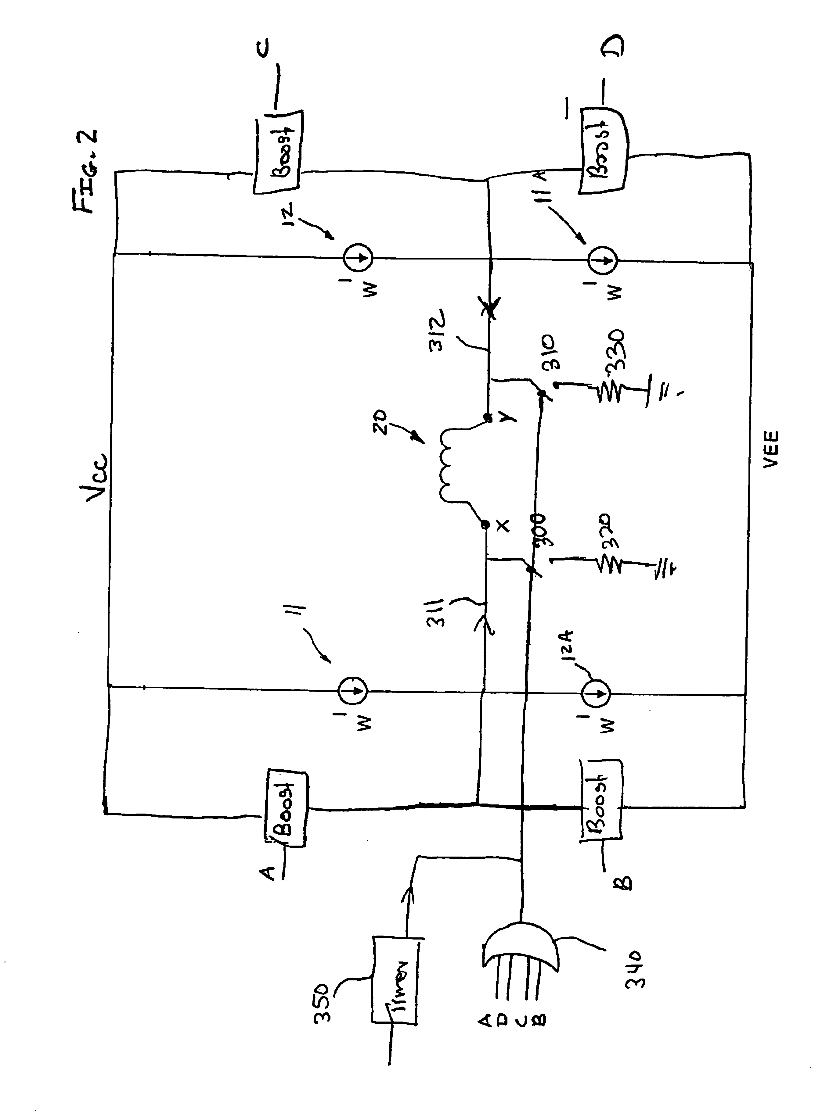
[0013]Referring now to FIG. 1 there is illustrated a simplified H-bridge type circuit typically used for driving current through a write ...


PUM

PropertyMeasurementUnit
currentaaaaaaaaaa
currentaaaaaaaaaa
currentaaaaaaaaaa

Abstract

A write driver apparatus and corresponding method for an inductive head element (20) in a magnetic storage medium, such as a hard disk drive, having an H-bridge type circuit (10) which is capable of driving a current through the inductive head element (20) and having a boost circuit (250, 260) which is coupled with the H-bridge (10) and which is operable for delivering another current during a predetermined period to the head element (20), wherein a sum of the currents provides the write current for the head element (20) of the hard disk drive. Further, a resistive element (210, 320, 330) is selectively coupled with the head element (20) for providing impedance matching in which the resistive element (210, 320, 330) is decoupled from the head element (20) during delivery of the current from the boost circuit (250, 260).

Description

FIELD OF THE INVENTION[0001]The present invention relates to magnetic storage mediums and, more particularly, to the write current driver for inductive heads used in the disk drives.BACKGROUND OF THE INVENTION[0002]Disk drives are employed to store large amounts of information in bits encoded on tracks on the disk in a series of logical 1's and 0's. These logical 1's and 0's are represented in bit cells, which are areas of uniform size along the length of the tracks on the disk. It is desirable that the information bits be encoded on the disk as densely as practical so that a maximum amount of information may be stored.[0003]Conventionally, logical 1's are recorded as transitions in magnetic flux on a magnetic disk for a given bit cell, and the absence of a transition indicates a logical 0. These transitions are created by switching the write current polarity through the write head. The density of the stored memory in a typical disk depends on how close the data can be written into ...

Claims


Application Information

Patent Timeline
Patent Type & Authority Patents(United States)
IPC IPC(8): G11B5/02G11B5/012G11B5/00
CPCG11B5/012G11B5/02G11B5/022G11B2005/0013
Inventor RANMUTHU, INDUMINI
Owner TEXAS INSTR INC
Why Eureka
Try Eureka