Device and method for decoding video signal

a video signal and decoding technology, applied in signal generators with optical-mechanical scanning, color televisions with bandwidth reduction, etc., can solve the problems of increasing the number of video decoding devices as many as is required for decoding a plurality of video bit streams, increasing the cost, not only the ic area, etc., and achieving the effect of reducing the display number

Inactive Publication Date: 2005-07-12
LG ELECTRONICS INC
View PDF9 Cites 140 Cited by
  • Summary
  • Abstract
  • Description
  • Claims
  • Application Information

AI Technical Summary

Benefits of technology

[0012]In another aspect of the present invention, there is provided a method for decoding a video signal, including the steps of (1) time multiplexing a plurality of video bitstreams in frames, to decode the bitstreams, (2) assigning a display number to every display frame of each of the video bitstreams according to a frame rate and a film mode, reading a data decoded in synchronization to a display synchronization signal from a memory and forwarding in a time multiplexing fashion, and reducing the display number, and (3) determining a video bitstream to be decoded at the present time among the plurality of video bitstreams according to a display state in the step (2).

Problems solved by technology

However, the use of a number of video decoders as many as required for decoding a plurality of video bit streams increases, not only an IC area, but also a cost.

Method used


Image

  • Device and method for decoding video signal
  • Device and method for decoding video signal
  • Device and method for decoding video signal

Examples


Embodiment Construction

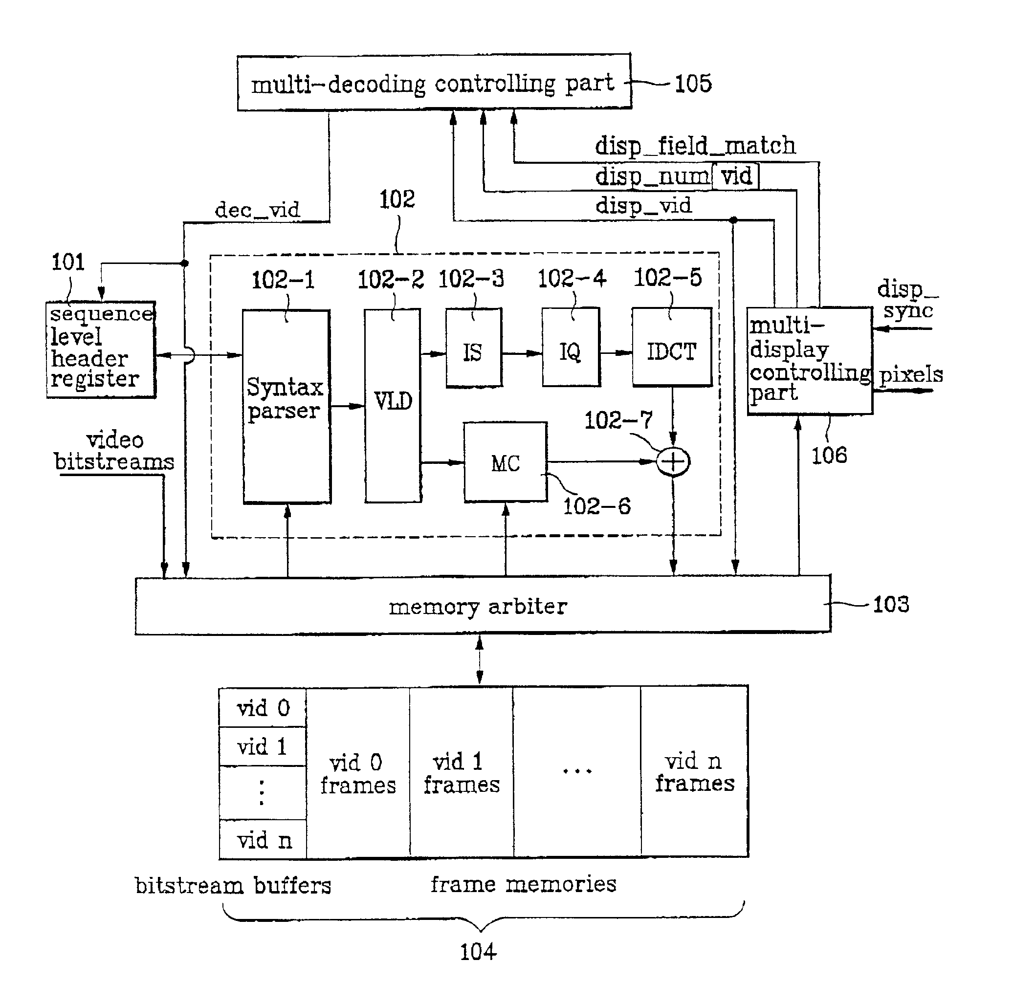
[0019]Reference will now be made in detail to the preferred embodiments of the present invention, examples of which are illustrated in the accompanying drawings. Currently, one video decoder is designed to decode only one video bit stream. Therefore, in a case when an SD (Standard Definition) class video is decoded by using a DTV video decoder which can decode an HD class video, only a portion of processing capability and a portion of memory of the DTV video decoder are used. The present invention suggests to make use of surplus processing capability and memory in the case of SD class video to decode a plurality of SD class videos on the same time by using one video decoder. FIG. 1 illustrates a block diagram of a system of a video decoder in accordance with a preferred embodiment of the present invention for carrying out such multi-decoding.

[0020]Referring to FIG. 1, the video decoder in accordance with a preferred embodiment of the present invention includes a sequence level heade...


PUM


Abstract

Device and method for decoding a plurality of video bitstreams on the same time by using one decoder by making time multiplexing decoding of bitstreams in different frame rates and film modes in frames, which facilitates simultaneous processing of multiple video bitstreams for PIP, POP, multi-channel broadcasting, and the like by using, not numerous video decoder, but only one HD class video decoded, a required memory size can be reduced significantly, and an IC size can be reduced further if the present invention is applied to an ASIC, that enhances competitiveness.

Description

BACKGROUND OF THE INVENTION[0001]1. Field of the Invention[0002]The present invention relates to a Digital TV(DTV) receiver, and more particularly, to device and method for decoding a plurality of video bitstreams on the same time by using one decoder.[0003]2. Background of the Related Art[0004]The MPEG(Moving Picture Experts Group)-2 video standards are widely used in compressing, transmission or storage, and reproduction of a video signal in DTV, or DVD (Digital Versatile Disc). Particularly, in the DTV, an MPEG-2 video decoder is required to decode an HD(High Definition) class video of MP@HL levels which is implemented by one ASIC (Application Specific Integrated Circuit). Recently, in addition to this, a number of video decoders are used for implementing a variety of DTV display fictions, such as PIP(Picture In Picture) and POP(Picture Out Picture), and efforts for putting the numerous video decoders into one ASIC are also made. The PIP is display of at least one subpicture with...

Claims


Application Information

Patent Timeline
Patent Type & Authority Patents(United States)
IPC IPC(8): H04N7/26H04N7/50
CPCH04N19/61H04N19/42E03D9/08E03C1/021F16K1/36
Inventor LYU, HWA YOUNG
Owner LG ELECTRONICS INC
Why Eureka
Try Eureka