Method for the reduction of combustion-driven oscillations in combustion systems and premixing burner for carrying out the method

a technology of combustion system and combustion system, which is applied in the ignition of turbine/propulsion engine, combustion type, lighting and heating apparatus, etc., can solve the problems of unsatisfactory periodic heat release within the combustion chamber, fuel at the head stage is accompanied by an increase in the emission of no/sub>x/sub>, and thermoacoustic oscillations present problems

Inactive Publication Date: 2005-07-19
ANSALDO ENERGIA IP UK LTD
View PDF13 Cites 66 Cited by
  • Summary
  • Abstract
  • Description
  • Claims
  • Application Information

AI Technical Summary

Benefits of technology

[0010]The object on which the invention is based is to provide a method for the reduction of combustion-driven thermoacoustic oscillations in combustion systems, in particular in those with low acoustic damping, which largely prevents the formation of coherent flow instabilities at the burner outlet, and to provide a premixing burner for carry ing out the method, which can be produced at a low outlay in terms of apparatus.
[0014]Advantageously, the fuel discharge takes place through at least one fuel nozzle orifice formed at the lance end, in such a way that the fuel discharged in the interior of the burner is mixed in a very finely distributed manner with inflow air and is at the same time swirled. In particular, due to the wake at the lance end, further stabilization of the aerodynamically generated backflow zone takes place. In particular, as a result of the fuel introduction according to the invention in a position shifted downstream within the burner interior, the flame forming within the backflow zone is prevented from periodically running out of the burner and running back into the latter. By the fuel discharge being in spatial proximity to the backflow zone forming within the combustion chamber, precisely that vortex breakdown can be assisted by the swirled fuel / air mixture spreading out in the flow direction, with the result that the backflow zone and consequently the flame are decisively stabilized.
[0017]In particular, when the premixing burner is operating with fuel being supplied via nozzles arranged along the casing into combustion air entering the burner interior tangentially, the measure according to the invention of partial fuel injection via the central fuel lance pushed into the interior contributes to the stabilization of the flame forming within the backflow zone.

Problems solved by technology

When turbomachines such as, for example, gas turbine plants are in operation, combustion-driven thermoacoustic oscillations often occur in the combustion chambers, these taking the form of fluidic instability waves at the burner and lead to flow vortices which greatly influence the entire combustion operation and lead to undesirable periodic heat releases within the combustion chamber.
This results in pressure fluctuations of high amplitude which may lead to undesirable effects, such as to a high mechanical load on the combustion chamber housing, to increased NOx emission as a result of inhomogeneous combustion or even to an extinguishing of the flame within the combustion chamber.
However, this method of reducing thermoacoustic oscillation amplitudes entails the disadvantage that the injection of fuel at the head stage is accompanied by an increase in the emission of NOx.
Investigations of the formation of thermoacoustic oscillations have shown that flow instabilities often lead to these instabilities.
Since this frequency coincides with typical fundamental characteristic modes of many annular burners in gas turbine plants, the thermoacoustic oscillations present a problem.

Method used


Image

  • Method for the reduction of combustion-driven oscillations in combustion systems and premixing burner for carrying out the method
  • Method for the reduction of combustion-driven oscillations in combustion systems and premixing burner for carrying out the method
  • Method for the reduction of combustion-driven oscillations in combustion systems and premixing burner for carrying out the method

Examples


Embodiment Construction

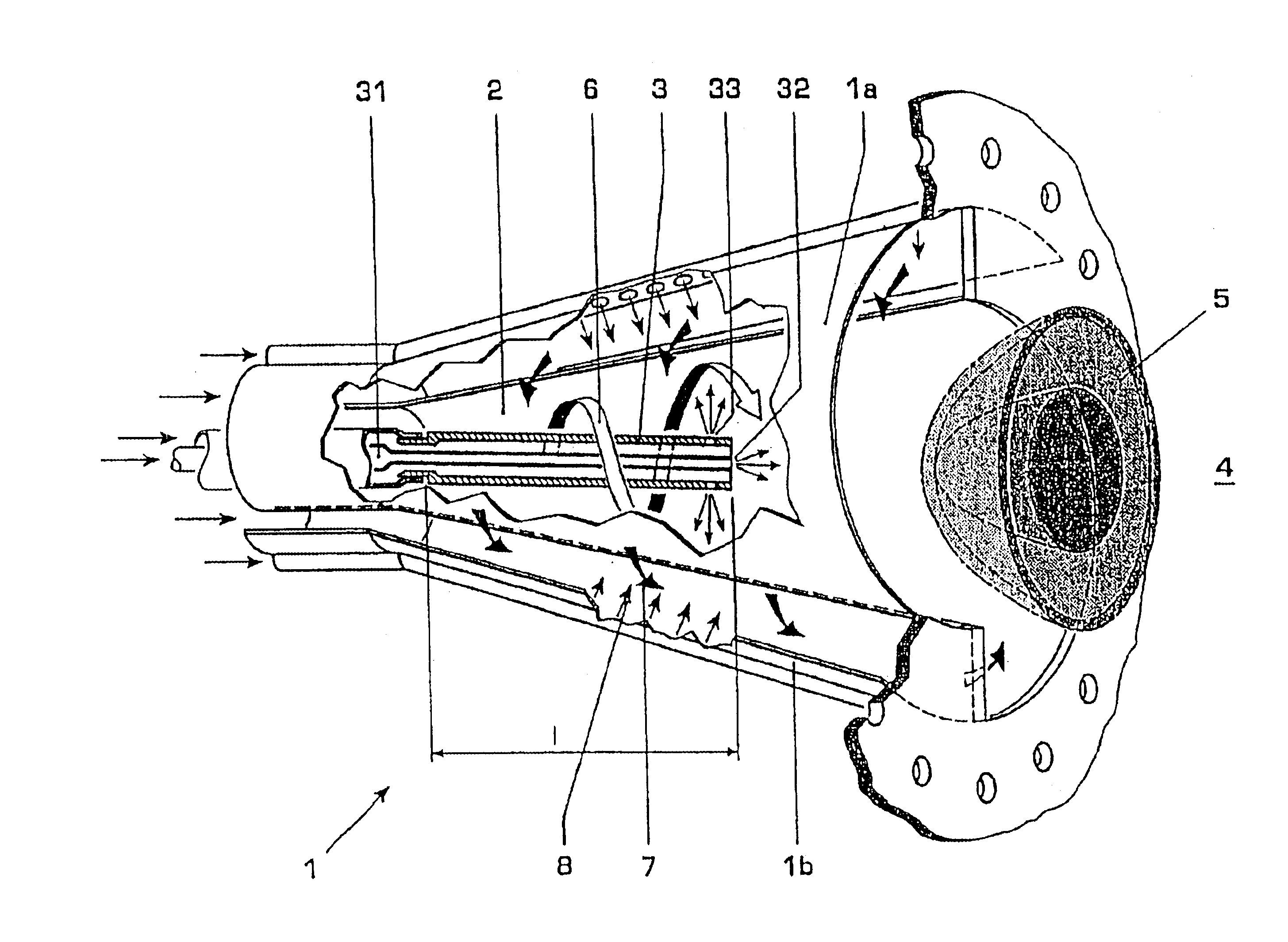
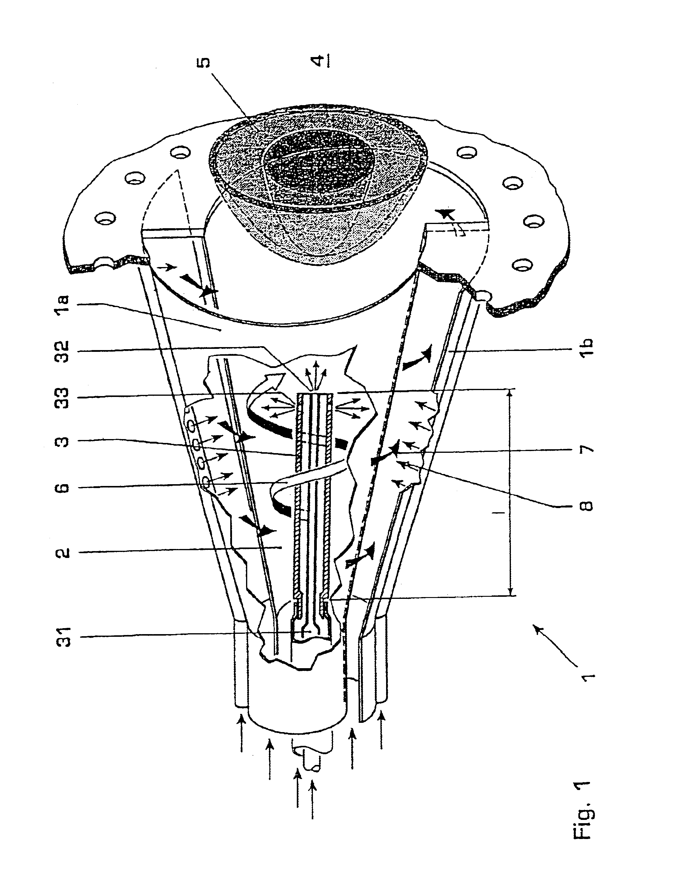
[0024]FIG. 1 illustrates in longitudinal section a premixing burner 1, such as may be gathered in terms of its basic construction, for example, from EP 0 321 809. The premixing burner 1 consists of two semimonocoque conically widening part bodies 1a and 1b which are arranged axially parallel, and offset to one another, in such a way that they form tangential gaps in two overlap regions located mirror-symmetrically opposite one another. The gaps resulting from the offset of the longitudinal axes of the part bodies 1a and 1b serve as inlet ducts, through which the combustion air 7 flows tangentially into the burner interior 2 when the burner is in operation. Located along these inlet ducts are injection orifices, through which a preferably gaseous fuel 8 is injected into the combustion air 7 flowing past. In addition to this fuel injection 8 at the burner casing, this above-mentioned generic type of burner possesses, centrally arranged in the initial region of the burner interior 2, a...


PUM


Abstract

A method and a device are described for the controlled damping of combustion-driven oscillations in a turbomachine with a burner system providing at least one burner, into which is introduced, via at least one burner nozzle arranged centrally in the burner, fuel which is intermixed with combustion inflow air flowing into the burner, to form a fuel / air mixture which is ignited in a combustion chamber following the burner system. The invention is distinguished in that the fuel nozzle is designed in the form of a burner lance, at the lance end of which fuel discharge into the burner takes place, and in that the burner lance projects into the burner in the amount of at least one third of the axial burner length.

Description

[0001]This application claims priority under 35 U.S.C. §§ 119 and / or 365 to Appln. No. 102 05 839.3 filed in Germany on Feb. 13, 2002; the entire content of which is hereby incorporated by reference.FIELD OF THE INVENTION[0002]The invention relates to a method for the reduction of combustion-driven oscillations in combustion systems, in particular in those with low acoustic damping, such as are often to be found in combustion chambers of turbomachines, and to a premixing burner for carrying out the method.BACKGROUND OF THE INVENTION[0003]When turbomachines such as, for example, gas turbine plants are in operation, combustion-driven thermoacoustic oscillations often occur in the combustion chambers, these taking the form of fluidic instability waves at the burner and lead to flow vortices which greatly influence the entire combustion operation and lead to undesirable periodic heat releases within the combustion chamber. This results in pressure fluctuations of high amplitude which ma...

Claims


Application Information

Patent Timeline
Patent Type & Authority Patents(United States)
IPC IPC(8): F23D14/74F23D17/00F23D11/40F23R3/28F23D14/72F23C7/00F23R3/18F23R3/12F23R3/30
CPCF23C7/002F23D11/402F23D14/74F23D17/002F23R3/286F23C2900/07002F23D2210/00F23R2900/00014
Inventor GUTMARK, EPHRAIMPASCHEREIT, CHRISTIAN OLIVER
Owner ANSALDO ENERGIA IP UK LTD
Why Eureka
Try Eureka