Lighted cutting tools

Inactive Publication Date: 2005-07-19
MAKITA CORP
View PDF41 Cites 34 Cited by
  • Summary
  • Abstract
  • Description
  • Claims
  • Application Information

AI Technical Summary

Benefits of technology

[0007]It is, accordingly, one object of the present teachings to provide improved cutting tools tha

Problems solved by technology

As a result, visibility through the window may be obscured and the illuminating effect of the light may be considerably degraded.
Accordingly, altho

Method used


Image

  • Lighted cutting tools
  • Lighted cutting tools
  • Lighted cutting tools

Examples


Embodiment Construction

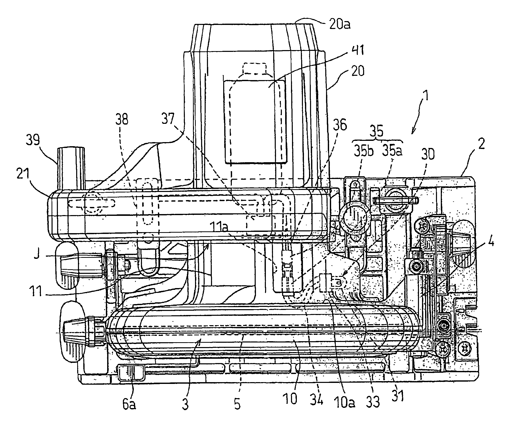
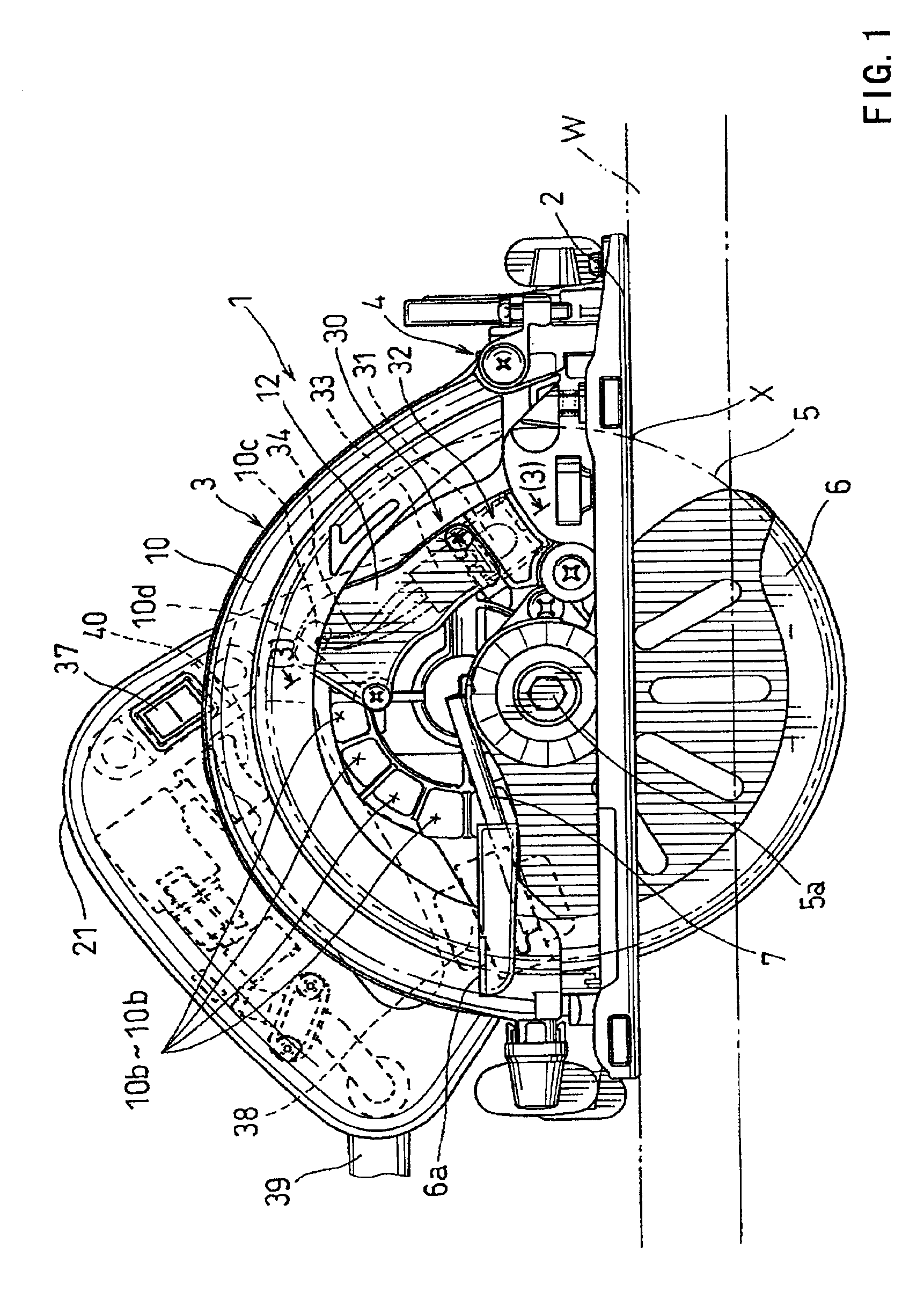
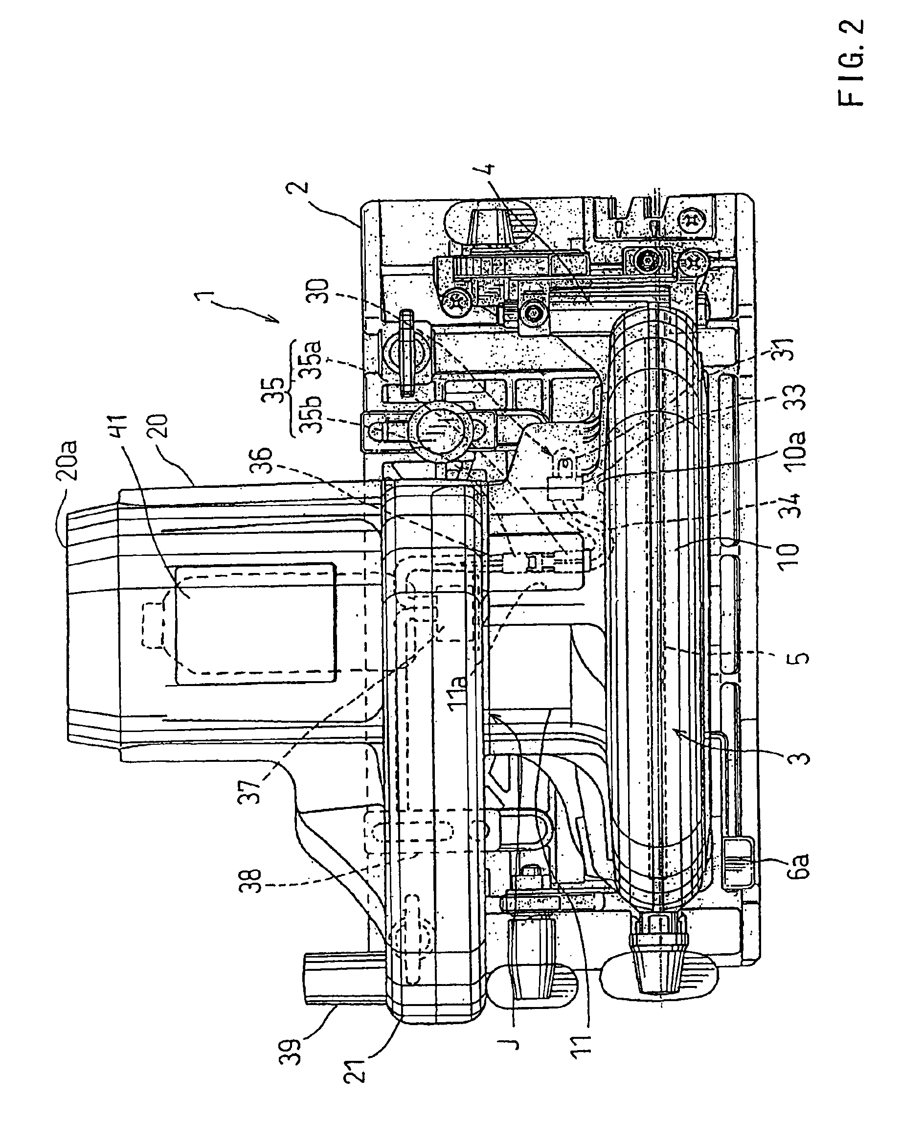
[0020]Cutting tools are taught that include a saw blade and a blade case adapted to cover the saw blade. A light is preferably provided to illuminate a portion of the workpiece that will be cut by the saw blade during a cutting operation. In one preferred embodiment, the light is mounted within the blade case and is laterally displaced from the saw blade. The direction of the light is preferably substantially parallel to the cutting direction of the saw blade. A mounting device optionally may be disposed within the blade case in order to hold the light.

[0021]Because the light is disposed laterally from the cutting direction of the saw blade, a substantial volume of the cutting chips do not reach the light during the cutting operation. Therefore, the light can effectively illuminate the cut position, even after extended operation of the cutting tool. In addition, because the light is mounted within the blade case, the light can be positioned much closer to the cut position than the l...


PUM


Abstract

A cutting tool includes a saw blade and a blade case adapted to cover the saw blade. A light may have a light for illuminating a portion of a workpiece that will be cut by the saw blade during a cutting operation. The light may be mounted within the blade case, so that the light is laterally displaced from the saw blade. A mounting device may be utilized to receive the light and the mounting device may be disposed within the blade case.

Description

BACKGROUND OF THE INVENTION[0001]1. Field of the Invention[0002]The present invention relates to cutting tools, and in particular to cutting tools having lights that serve to illuminate a portion of a workpiece that will be cut during a cutting operation.[0003]2. Description of the Related Art[0004]Japanese Laid-Open Utility Model Publication No. 60-98602 teaches a portable circular saw that includes a lighting device. The lighting device includes an incandescent light bulb that is disposed on the outer side of a blade case. The blade case serves to partially cover a circular saw blade and has a transparent window that is formed adjacent to the light bulb. Thus, a portion of a workpiece that will be cut can be illuminated by the light from the light bulb through the transparent window and through the inner space of the blade case.[0005]However, the transparent window is disposed on a surface that is tangential to the saw blade. Therefore, the transparent window directly opposes the ...

Claims


Application Information

Patent Timeline
IPC IPC(8): B23D59/00B23Q17/24B27B9/00B23D45/16B23D47/00
CPCB23D59/00B23Q17/2404B27B9/00Y10T83/04Y10T83/7705Y10T83/828Y10T83/853Y10T83/856
Inventor OKOUCHI, KATSUMI
Owner MAKITA CORP
Why Eureka
Try Eureka