High rate induction system

a sorter and high-rate technology, applied in the direction of sorting, mechanical conveyors, conveyor parts, etc., can solve the problems of inability to the sorter becomes starved, and the sorter cannot meet the rated throughput, so as to improve the performance of the sorter and improve the supply of products.

Inactive Publication Date: 2005-07-19
DEMATIC
View PDF22 Cites 39 Cited by
  • Summary
  • Abstract
  • Description
  • Claims
  • Application Information

AI Technical Summary

Benefits of technology

The present invention is a sortation system and a method of inducing it that improves the performance of the sorter by ensuring better supply of products to it.

Problems solved by technology

The technical problem addressed in this patent is how to induce product to a sorter at a rate that matches the throughput of the sorter, even when there is no accumulation upstream of the sorter or when the conveyors are of the belt variety. The invention proposes a method and apparatus for achieving this goal.

Method used


Image

  • High rate induction system
  • High rate induction system
  • High rate induction system

Examples


Embodiment Construction

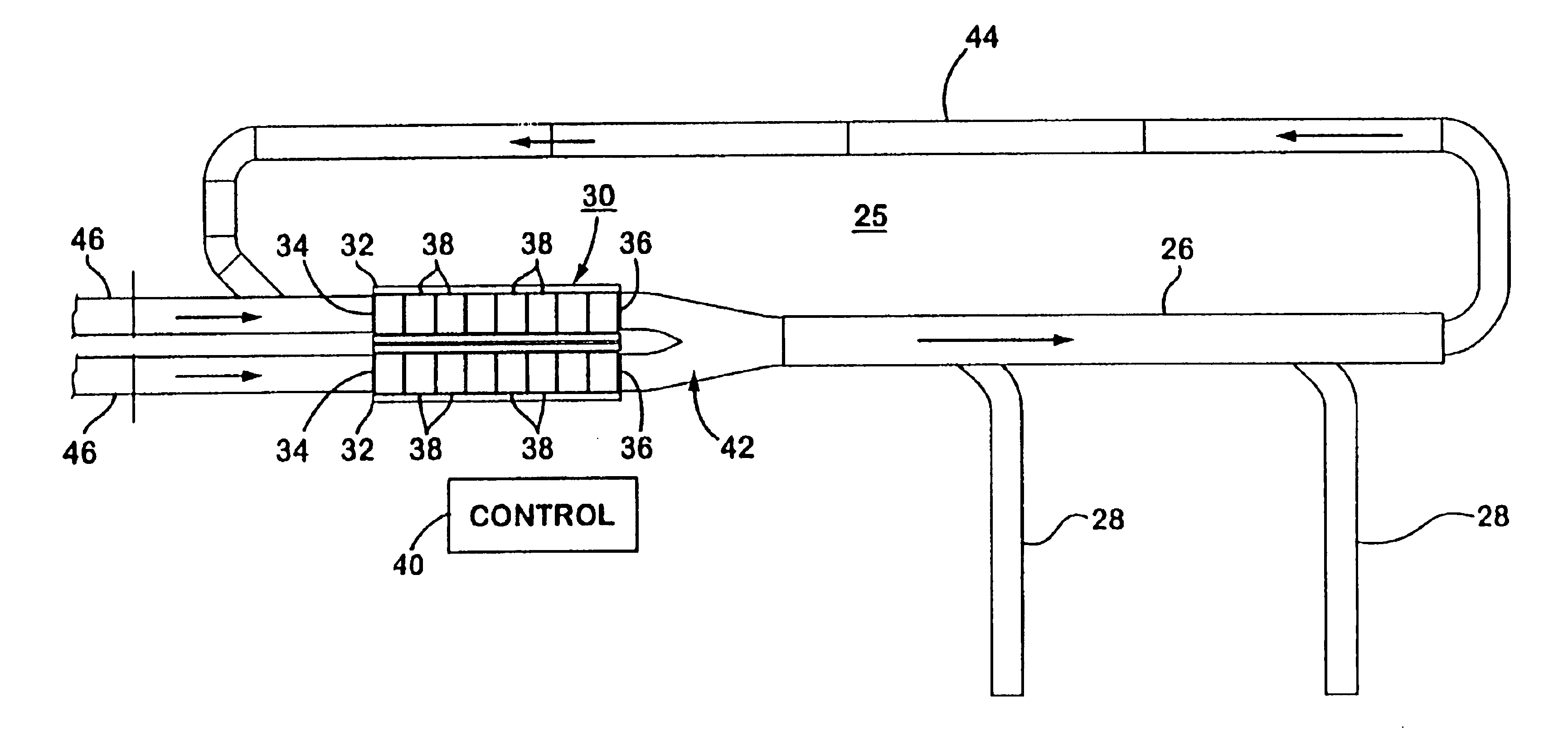
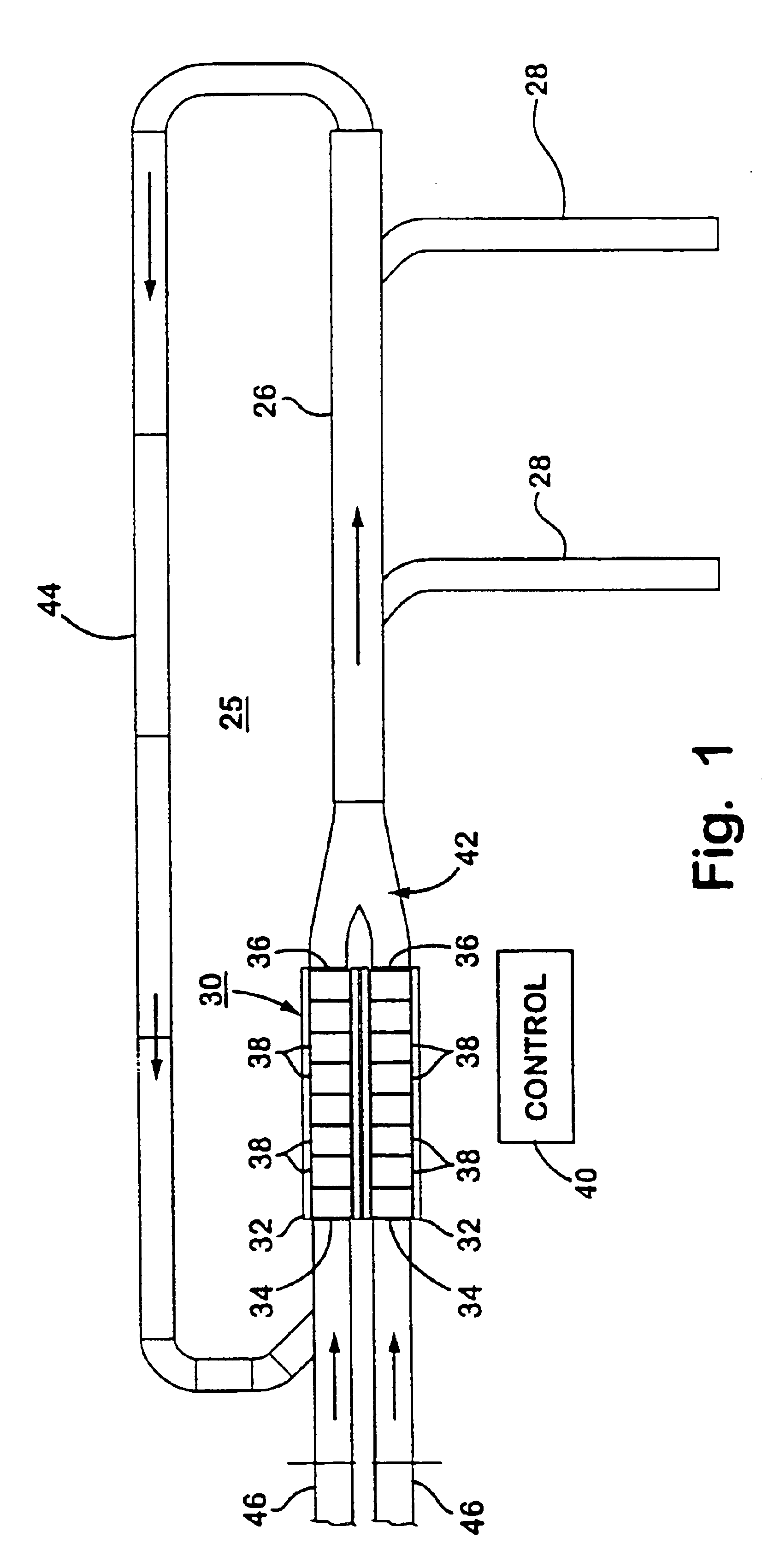
[0037]Referring now specifically to the drawings and the illustrative embodiments depicted therein, a high rate induction system 30 is used with a sortation system 25 including a continuous member 26 and a plurality of sort destinations 28 for receiving products discharged from the continuous member (FIG. 1). In the illustrative embodiment, continuous member 26 is a sortation conveyor and, preferably, a positive displacement sortation conveyor utilizing pusher shoes which travel with the conveying surface, as disclosed in commonly assigned U.S. Pat. No. 5,127,510 entitled MODULAR DIVERTER SHOE AND SLAT CONSTRUCTION, the disclosure of which is hereby incorporated herein by reference. However, the invention is useful with other types of sortation systems known in the art such as tilt wheel sorters, transverse belt sorters, stationary pusher sorters, and the like. Sort destinations 28 may include takeaway conveyors, chutes, or the like, on one or both sides of continuous member 26.

[003...


PUM


Abstract

A sortation system and method of inducting product are useful with a sorter having a continuous member defining a plurality of transport positions of the continuous member and a plurality of sort destinations for receiving product discharged from the continuous member. At least one induction unit is provided including a plurality of tandem conveying units. Product is received with the at least one induction unit from a product source and discharged from the at least one induction unit to the continuous member. According to one aspect of the invention, the at least one induction unit follows the speed of the continuous member. This includes starting as soon as the continuous member is moving and decreasing in speed substantially only when the continuous member decreases in speed. The invention is useful with linear sorters, such as positive displacement sorters, and the like. The invention is also useful with carousel sorters, such as tilt-tray sorters and cross-belt sorters.

Description


Claims


Application Information

Patent Timeline
Owner DEMATIC
Why Eureka
Try Eureka