
Internal broach

a broach and internal technology, applied in the field of internal broaches, can solve the problems of insufficient profile accuracy and flank surface quality, negative influence of flank curve accuracy, and considerable drawbacks

Inactive Publication Date: 2005-07-19
FORST TECH
View PDF7 Cites 14 Cited by
  • Summary
  • Abstract
  • Description
  • Claims
  • Application Information

AI Technical Summary

Benefits of technology

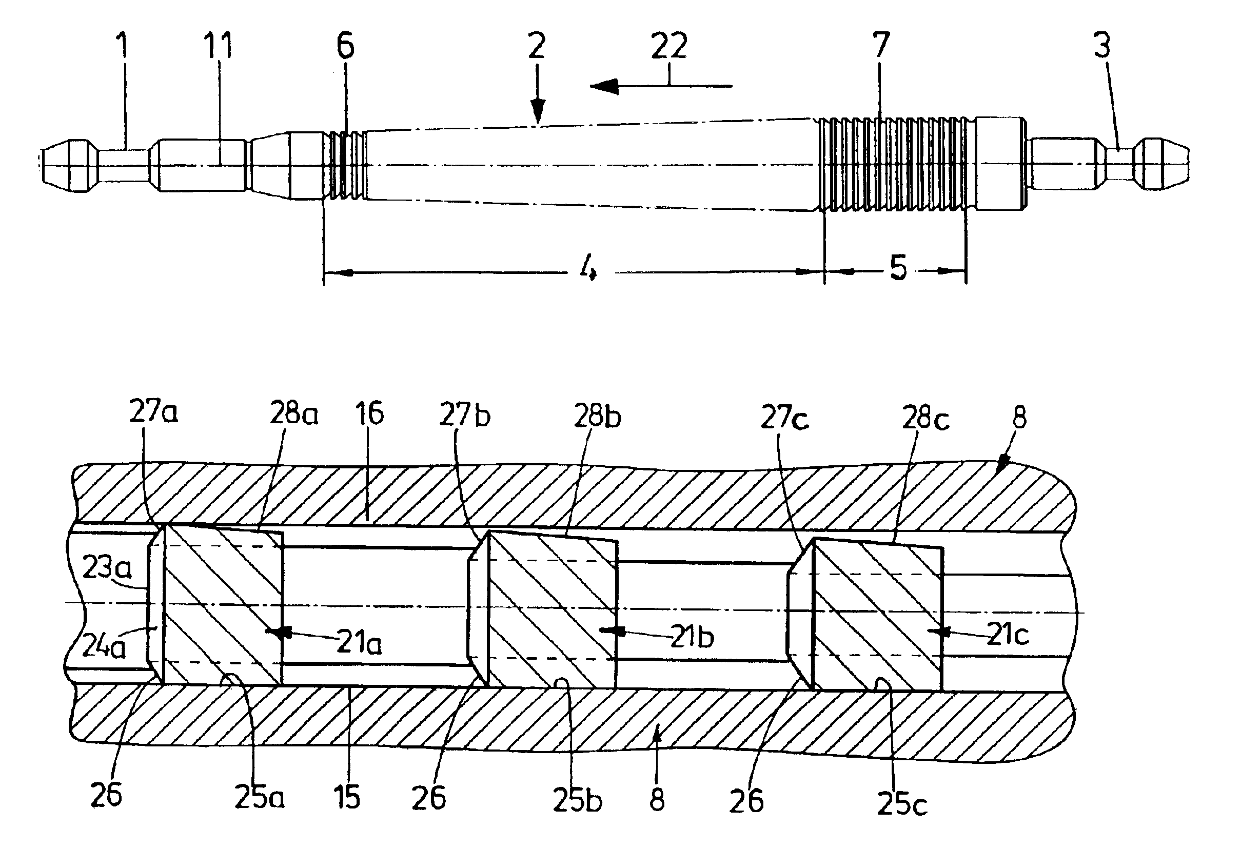
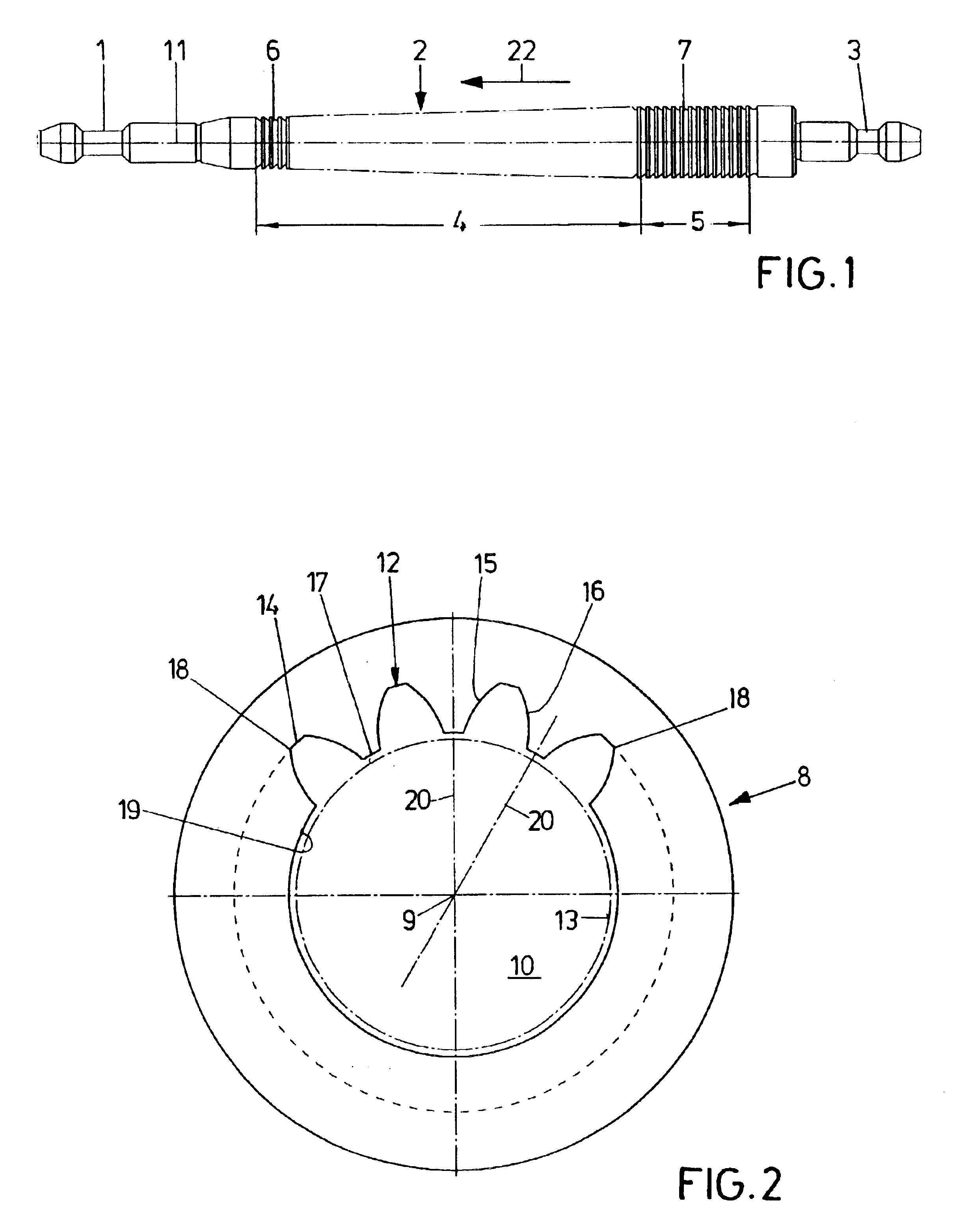
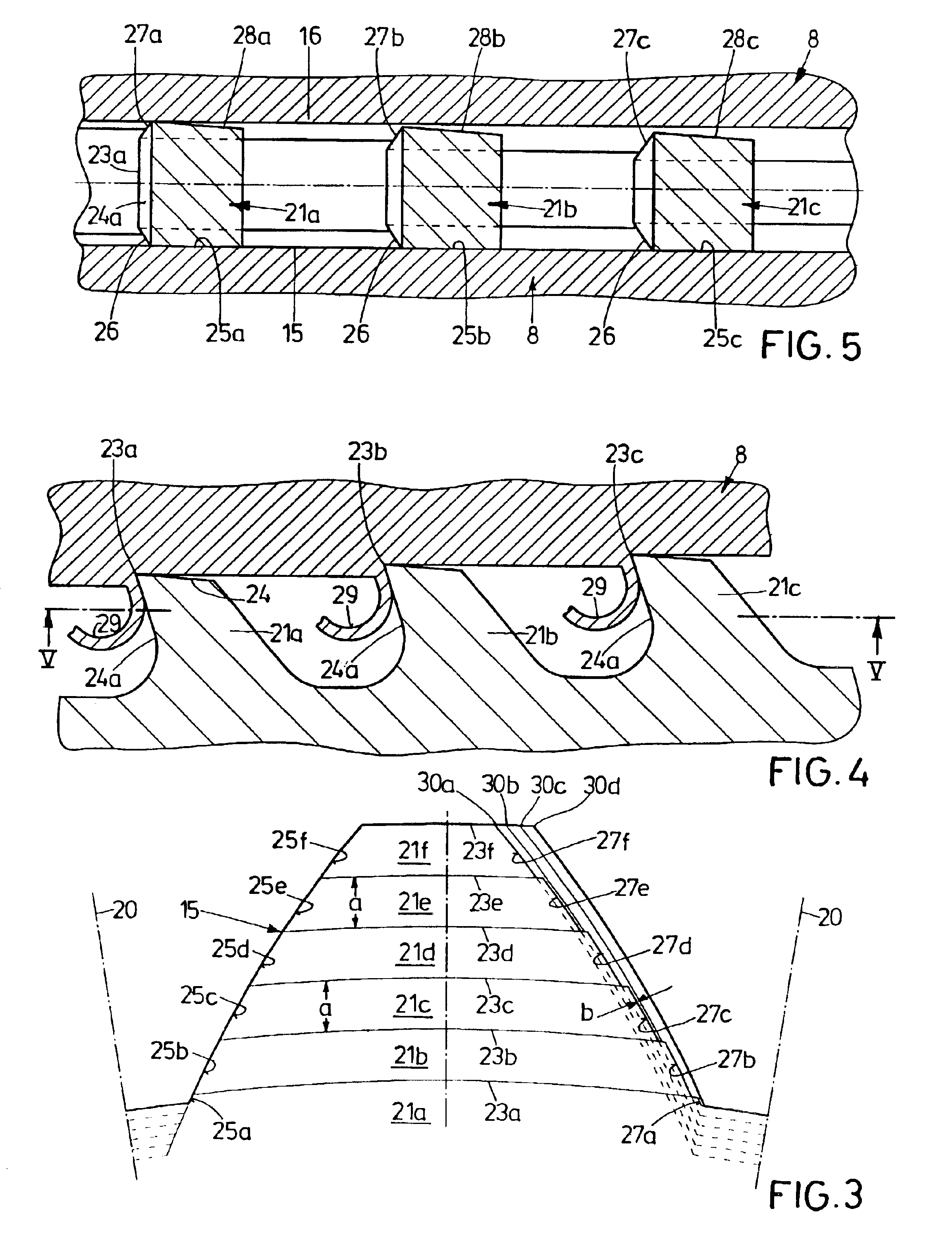
[0012]According to the invention, this object is attained by the features wherein the first sides are guide flanks, with the first edges being guide edges without cutting ability; and wherein the second sides, at least in proximity to bottom cutting blades, are flank-cutting-blade relief surfaces, the second edges, by allocation to the bottom cutting blades, being flank cutting blades with cutting ability. In the internal broach according to the invention, guidance takes place exclusively on one side of the broach cutting teeth i.e., no profile flank chip is machined. However, shaping of the chip that is cut by the bottom cutting blade i.e., the primary blade, takes place also in the vicinity of the guide edge to the extent it extends over the pitch of the profile. A chip can be cut on the opposite flank of the p

Problems solved by technology

Very often, profile accuracy and flank surface quality are not sufficient in this case, flank curve accuracy being satisfactory as a rule.
This is due to the fact that the relief-ground flank cutting blades of the sizing teeth are sharp cutting edges of comparatively bad self-guidance behavior.
It is inherent in the system that any changeover from a progressively stepped broaching operation to full form sizing is accompanied with a break in the broaching force, which leads to considerable drawbacks, in particular in the case of twist broaching.
This change may be sufficiently strong so that the full form sizing section is not led correctly into the progressively broached profiles and, as a result, machines the flanks unilaterally so that the profile is not sized on both flanks.
Owing to the mentioned deficiencies of the profile produced by progressively stepped broaching, the flank cutting blades of the broach cutting teeth will cut irregularly into the stepped flanks of the profile, with torsional vibrations originating which may negatively affect flank curve accuracy.
In the case of great height of the profiles that are to be produced, this will lead to wide spacings of teeth, which has the consequence that, with a given number of broach cutting teeth, the broach becomes too long.
If however the spacing of teeth is reduced in spite of too great a height of the profile that is to be produced, this may lead to grinding problems.

Method used


Image

  • Internal broach
  • Internal broach
  • Internal broach

Examples


second embodiment

[0034]In the second embodiment according to FIGS. 6 to 8, identical parts have the same reference numerals as in the above embodiment. In as much as the parts function identically but differ in construction, the same reference numerals are used provided with a prime.

[0035]This second embodiment differs from the one specified above by the course of the flank cutting blades 27′a to 27′f of the broach cutting teeth 21′a to 21′f. They are full size cutting, having no flank pitch; the flank pitch is zero. The flank cutting blades 27′a to 27′b form the chip 29 and the flank 16 along the area of a pitch a. The course of the flank cutting blades 27′a to 27′f is precisely parallel to the course of the flank 16. Broaching to size takes place by means of the sizing teeth 30a to 30d over the full depth of the profile.

third embodiment

[0036]In the third embodiment according to FIGS. 9 to 11, parts that are identical to the mentioned embodiments have identical reference numerals, whereas parts that are functionally identical but differ in construction have the same reference numerals provided with a double prime. In this case, the flank cutting blades 27″a to 27″f are full size cutting blades. The successive broach cutting teeth 21″a to 21″f have a positive flank pitch b″, to which 027″a to 27″f cut a chip 31 over the profile depth that has been machined in each case. This is followed by a broaching-to-size operation of this flank 16, which is however not absolutely necessary. Flank full size cutting, as illustrated for the flank 16 in the embodiment of FIGS. 9 to 11, has been described in U.S. Pat. No. 5,865,569 for the job of simultaneously cutting both flanks.

[0037]FIGS. 12 and 13 on the one hand and FIGS. 14 and 15 on the other illustrate two broach cutting teeth 21g and 21h, with the represented pitch a being...

first embodiment

[0038]In modification of the first embodiment according to FIGS. 3 to 5, FIGS. 12 and 13 illustrate that the side, provided with a flank cutting blade of cutting ability, of the respective broach cutting teeth 21g, 21h has a partial flank cutting blade 32g, 32h only over the depth of some few pitches a. Therebehind, these sides are relieved surfaces 33g, 33h i.e., they are not covered by the desired flanks 16 that are to be produced; they do not engage with the work piece 8. FIGS. 14 and 15 illustrate a case in which also the flank 16 is broached to size by the broach cutting teeth 21, there being no need for final sizing. As opposed to that, the flank 16 of the embodiment according to FIGS. 12, 13 is finished by sizing. Relieving reduces the risk of clamping in the same way as the relief produced by grinding.


PUM

PropertyMeasurementUnit
Timeaaaaaaaaaa
Timeaaaaaaaaaa
Timeaaaaaaaaaa

Abstract

An internal broach for internally broaching profiles, defined by a bottom and flanks, of female serrations of a work piece, comprises a toothed portion with several rows of broach cutting teeth disposed successively counter to a direction of broaching, successive broach cutting teeth being allocated to each other for broaching a profile. The broach cutting teeth have bottom cutting blades and first and second sides. The first sides are guide flanks, the edges of which are guide edges without cutting ability. The second sides are flank-cutting-blade relief surfaces, the edges of which are designed as flank blades with cutting ability.

Description

BACKGROUND OF THE INVENTION[0001]1. Field of the Invention[0002]The invention relates to an internal broach for internally broaching profiles defined by a bottom and flanks, in particular female serrations, in a work piece, which broach comprises a shank, which leads in a direction of broaching; and a toothed section with several rows of broach cutting teeth, the rows being disposed successively counter to the direction of broaching; wherein broach cutting teeth are allocated to each other for broaching a profile of a depth; wherein the broach cutting teeth have bottom cutting blades and first and second sides; wherein the bottom cutting blades of successive and associated broach cutting teeth have a pitch a relative to the broach cutting teeth which lead in the direction of broaching; wherein a bottom-cutting-blade relief surface is allocated to the bottom cutting blades; and wherein the first and second sides pass through the bottom-cutting-blade relief surfaces, forming first and...

Claims


Application Information

Patent Timeline
IPC IPC(8): B23F21/26B23F21/00B23D43/02B23D43/00
CPCB23D43/02B23F21/26Y10T407/1671Y10T407/16
Inventor BERKTOLD, ANDREASWEGHAUS, NORBERT
Owner FORST TECH
Learn More